6-4 Planning the electrical connections DKR Drive Controllers
DOK-DIAX03-DKR********-PR02-EN-P
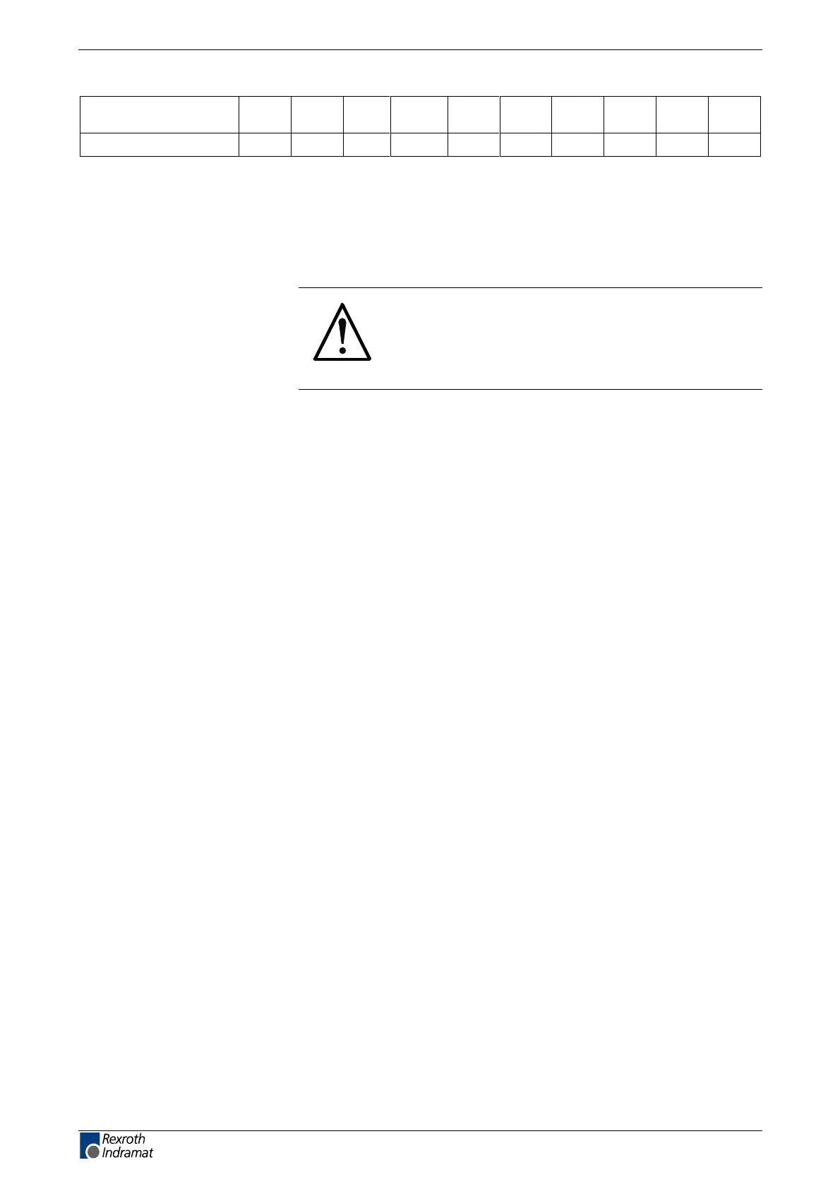
terminal connector
designation
X2 X3 X4 X5 X6 X7 X8 X9 X10 X11
lead cross sections
1,5 *2 10...35
*1
2,5 2,5 2,5 2,5 10
*1: finely stranded
*2: cable assembly made by Rexroth Indramat
Fig. 6-3: Lead cross sections [mm²]
6.4 Mains connection
CAUTION
Failure or malfunction caused by a FI current
limiting type circuit breaker!
⇒
Do not mount FI current limiting type circuit breakers
in the power supply lead to the drive.
The following applies to the mains input terminal connectors of the drive:
•
X5/L1, L2, L3: 3xAC 400 ... 480 V,
±
10 %; 50 ... 60 Hz,
±
2 Hz
•
X10/L, N: 1xAC 230 V,
±
10 %; 50 ... 60 Hz; 200 VA (or. 300 VA)
The devices are type-tested according to EN61 800-3 (industrial area);
i. e. the voltage peaks of the mains voltage must not exceed the following
values:
•
1 kV phase/phase and
•
2 kV phase/earth
Grounded three-phase systems
The drive can be connected either to grounded star systems or external
conductor three-phase systems directly.
If the mains voltage is not compatible with the permissible rated power
voltage, then an autotransformer for matching the voltages must be
implemented.
Permissible rated voltage
Periodic overvoltage
Direct mains connection
LSA Control S.L. www.lsa-control.com comercial@lsa-control.com (+34) 960 62 43 01