DKR Drive Controllers Planning the cabinet 5-11
DOK-DIAX03-DKR********-PR02-EN-P
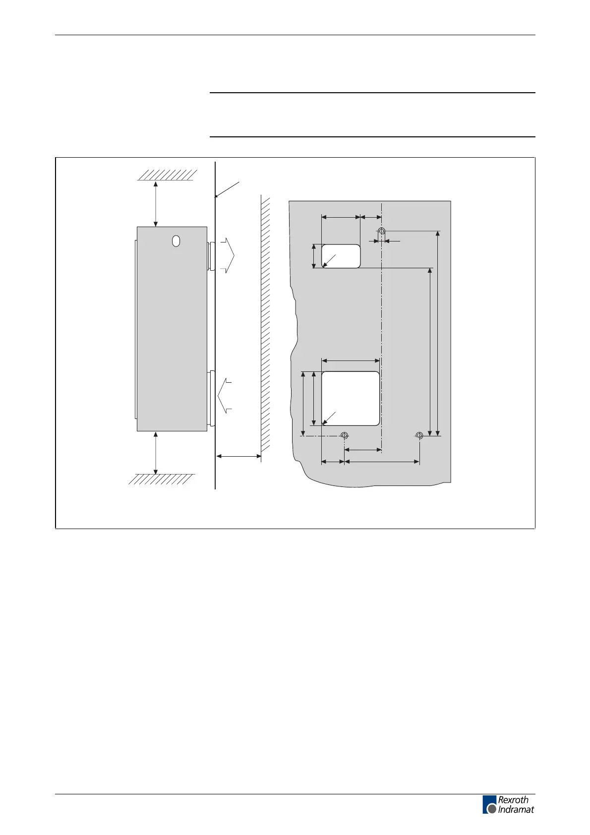
Distances, drill diagram and vents
Note: The vents in the back wall of the cabinet or mounting panel
are only required if the drive is cooled with air from outside the
unit.
zMALKDKR2
115 ±0,5 63
M8
68±0,5
R10
869
976
-1
176 ±0,5
157 ±0,5
185
270 ±0,5
135
68
R10
Looking from outside of control enclosure onto rear wall or mounting panel.
All dimensions in mm.
min. 80
air outlet
air inlet
M8M8
min. 80
min. 80
control enclosure rear wall
or mounting panel
Fig. 5-10: Distances, drill diagram and vents for the DKR 02
LSA Control S.L. www.lsa-control.com comercial@lsa-control.com (+34) 960 62 43 01