DKR Drive Controllers Planning the electrical connections 6-15
DOK-DIAX03-DKR********-PR02-EN-P
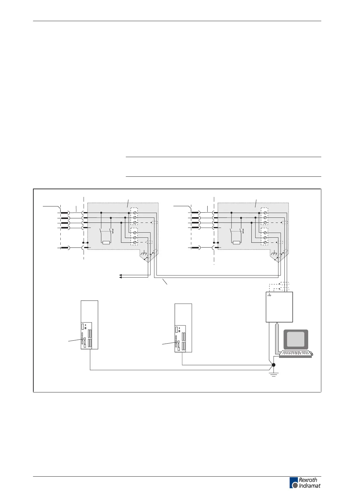
RS-485 interface
The RS-485 interface enables:
•
the implementation of a serial bus with up to 31 participants connected
via a two-wire line (half duplex mode), i. e., it can be used to start up
several DKCs with DriveTop without having to plug into a different
socket of the interface cable,
•
a transmission length of up to 500 meters,
•
transmission rates of 9600/19200 baud and
•
the implementation of central PC-supported visualization unit.
As a matter of principle, there are two solutions for operation with RS-485:
•
RS-232/RS-485 converter between PC and drives or
•
RS-485 plug-in card in PC.
Note: Please contact your PC supplier to find the solution for your
application.
X2
4
RS485+
5
RS485-
7
SGND
12
+5V
1
2
3
1
2
3
X1
X2
Axis 1
X2
4
5
7
12
1
2
3
1
2
3
X1
X2
PC
1)
RS 485
1)
2)2)
3) 3)
Aprs485.fh7
A B
0V
150
150
RS-232/RS-485 converter or
PC plug-in card
INS0644
INK0572
to further
devices
GND
IKB003
Axis 2
RS485+
RS485-
SGND
+5V
GND
10 10
X2
INS0644
IKB003
4
5
7
12
10
4
5
7
12
10
X2
1): Connector outer screen to ground potential (strain relief of metallic
connector case) on PC side and on device.
2): Connection of device ground with the connector case with the fixation
screws of the connector.
3): If the drive controller is fitted as the geometrically last participant of a
RS485 bus, activate the bus termination.
Fig. 6-16: Example on how to connect an RS-485 interface
LSA Control S.L. www.lsa-control.com comercial@lsa-control.com (+34) 960 62 43 01