4A-1990-13645--2 495 POWERHEAD
Check Valves
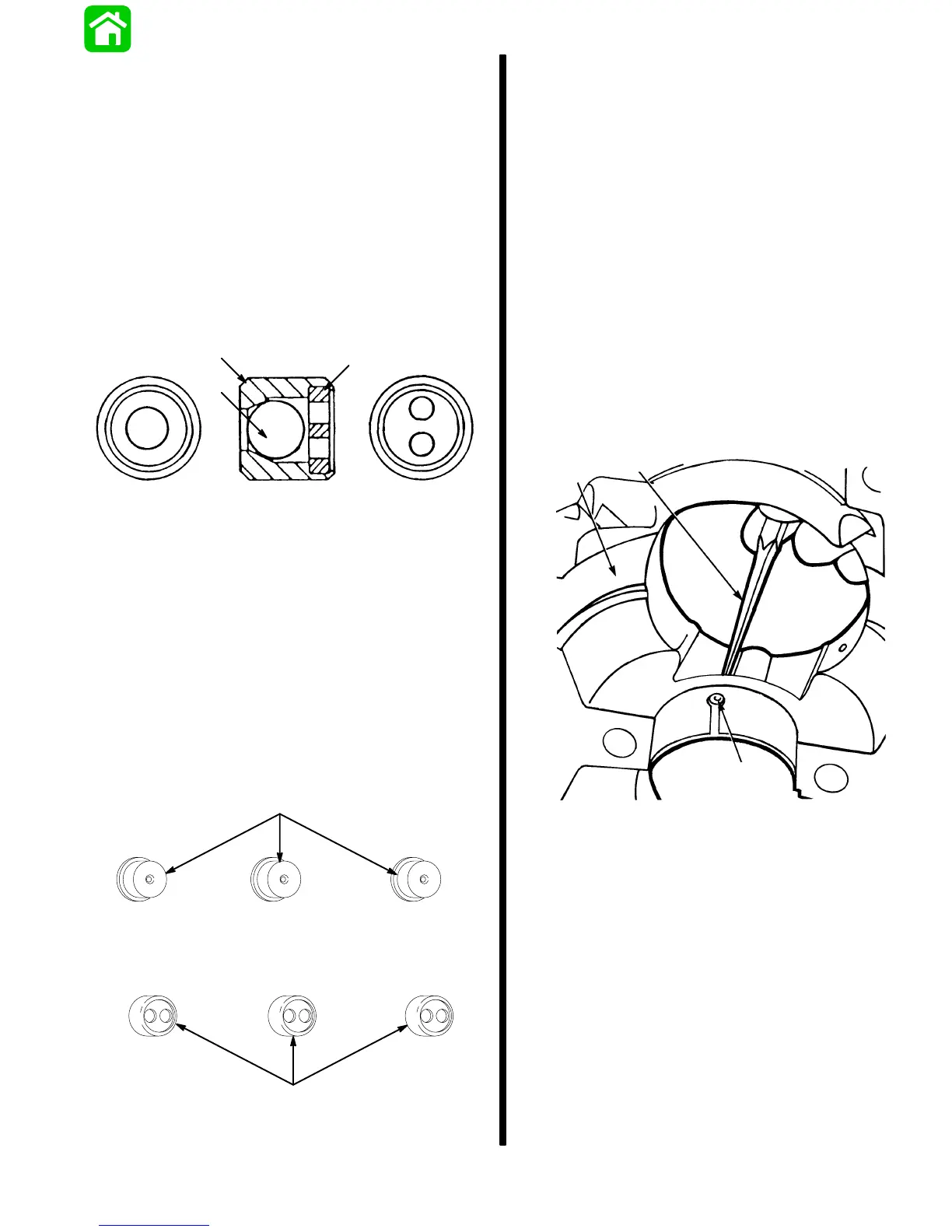
DESIGN I (MODELS WITH CHECK VALVE ONLY)
Located in crankcase cover under center main
bearings.
These can be damaged by hot combustion blow-by
into crankcase.
To Check: Look through hole - if you see light, the ny-
lon ball is bad - probably melted; REPLACE valve. If
you see no light, insert fine wire into check valve hole
to see if there is slight movement of the nylon ball; if
ball moves, valve is o.k. otherwise, replace check
valve.
b
c
a
a - Check-Valve Body
b - Nylon Ball
c - Ball Retainer
IMPORTANT: If it is determined that the check
valves must be replaced or that restrictors are not
installed with the check valves, it is recom-
mended that the Bleed Check Valve/Restrictor Kit
(22-814204A1) be installed.
DESIGN 2 (MODELS WITH CHECK VALVE AND
RESTRICTOR)
BLEED CHECK VALVE/RESTRICTOR KIT
(22-814204A1)
COMPONENTS CONTAINED IN KIT:
25704
a
b
a - Bleed Check Valve (3 Each)
b - Restrictor (3 Each)
This kit is for use in three cylinder 71 cubic inch 70, 75,
80 and 90 horsepower models and four cylinder 105
cubic inch 100 and 115 horsepower models.
NOTE:
Three cylinder and four cylinder outboards
with starting serial number OC123214 and above
have these kits installed from factory.
Installation Instructions:
1. Referring to appropriate service manual, remove
powerhead from driveshaft housing.
2. Remove all assemblies as required to obtain ac-
cess to crankcase cover.
3. Remove crankcase cover from cylinder block.
4. Using a 5/32″ (3.9mm) punch, carefully tap bleed
check valves out of crankcase cover. (Tap check
valve towards crankshaft side of crankcase
cover.)
25703
a
b
c
a - Crankcase Cover
b - Bleed Check Valve
c - Punch (5/32”- 3.9mm)
NOTE:
Three cylinder models will require TWO bleed
check valves and TWO restrictors. Four cylinder mod-
els will require THREE bleed check valves and
THREE restrictors.
5. With FUNNEL SHAPE side of restrictor facing
crankshaft side of crankcase cover, carefully tap
restrictor into crankcase cover until seated.
6. With ONE HOLE side of bleed check valve facing
crankshaft, carefully tap check valve into crank-
case cover until seated against restrictor. BE
CAREFUL NOT TO OVERSEAT CHECK VALVE
as check valve case may distort and valve will not
function properly.