90-13645--2 4952B-16 ELECTRICAL AND IGNITION
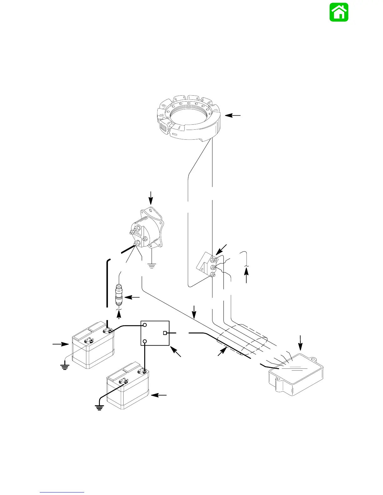
4 Cylinder Battery Charging Diagram
with Battery Isolator (Small Voltage
Regulator)
IMPORTANT: After electrical connections are
made, coat all terminal connections using Quick-
silver Liquid Neoprene (92-25711), to avoid corro-
sion.
51050
Large Red
(Output) Lead
BLK BLACK
BLU BLUE
GRY GRAY
RED RED
YEL YELLOW
YEL
YEL
RED
YEL
YEL
GRY
GRY
YEL
YEL
RED
RED
GRY
RED
RED
RED
B1
B2
RED
A
Small
Red (Sense)
Lead
a
b
c
d
e
f
g
h
i
j
a - Stator
b - Terminal Block
c - To Tachometer
d - Voltage Regulator/Rectifier
e - Battery Isolator
f - Auxiliary Battery
g - Start Battery
h - To Remote Control Harness
i - 20 Ampere Fuse
j - Starter Solenoid