90-13645--2 1095 2A-3ELECTRICAL AND IGNITION
Ignition System Test Chart
IMPORTANT: BEFORE attempting the ignition system checks, following, thoroughly read the preceding
pages of these instructions to become familiar with the proper Automatic Distributorless Ignition (ADI)
test sequence and procedures (particularly any “Safety Warnings” and “Cautions”). ALL tests are per-
formed with lead wires connected – terminals exposed. SWITCH BOX MUST BE GROUNDED (CASE TO
ENGINE BLOCK) FOR ALL TESTS – IF NOT, SWITCH BOXES MAY BE DAMAGED.
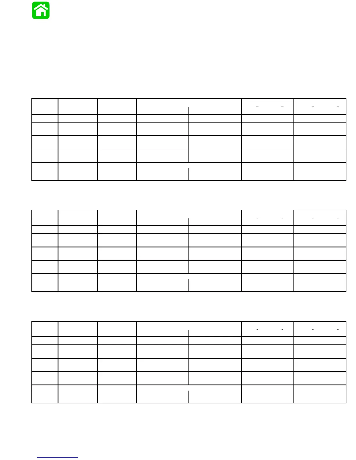
3 Cylinder Stators – 398-9710A13/14/28 and all 398-8778A– Stators
4 Cylinder Stators – 398-9710A15/31 and all 398-8778A– Stators
ADI Test Selector Sw.
DVA Leads
Volta
e Readin
Volta
e Readin
Seq.
Test
Position
Red Black
@ 300-1000 RPM
@ 1000-4000 RPM
1-A Coil Primary 400 VDC* Coil (+) Terminal Coil (–) Terminal 150-250 180-280
2-A
Sw. Box –
Stop Circuit
400 VDC*
Black/Yellow (3)
Sw. Box Terminal
Ground 200-360 200-360
3-A
4-A
Stator –
Low Speed
400 VDC*
Blue Sw.
Box Terminal
Ground 200-300 200-330
3-A
4-A
Stator –
High Speed
400 VDC*
Red Sw.
Box Terminal
Ground 20-90 130-300
[See Note (1)]
5-A
w.
ox –
Bias
or
40 VDC
Ground
White/Black
Sw. Box Terminal
2-10 10-30
(1) Using meter only, REVERSE LEAD POLARITY; connect leads as specified.
* If using a meter with a built-in DVA, place selector switch in the DVA/400 VDC position.
3 Cylinder Stator – 9 Ampere 398-9873A21 & 15 Ampere 398-9873A24
ADI Test Selector Sw.
DVA Leads
Volta
e Readin
Volta
e Readin
Seq.
Test
Position
Red Black
@ 300-1000 RPM
@ 1000-4000 RPM
1-A Coil Primary 400 VDC* Coil (+) Terminal Coil (–) Terminal 145-250 210-240
2-A
Sw. Box –
Stop Circuit
400 VDC*
Black/Yellow (3)
Sw. Box Terminal
Ground 215-340 280-320
3-A
4-A
Stator –
Low Speed
400 VDC*
Blue Sw.
Box Terminal
Ground 215-340 280-320
3-A
4-A
Stator –
High Speed
400 VDC*
Red Sw.
Box Terminal
Ground 10-55 45-255
[See Note (1)]
5-A
w.
ox –
Bias
or
40 VDC
Ground
White/Black
Sw. Box Terminal
2-30 10-30
(1) Using meter only, REVERSE LEAD POLARITY; connect leads as specified.
* If using a meter with a built-in DVA, place selector switch in the DVA/400 VDC position.
4 Cylinder Stator – 16 Ampere 398-9710A33
ADI Test Selector Sw.
DVA Leads
Volta
e Readin
Volta
e Readin
Seq.
Test
Position
Red Black
@ 300-1000 RPM
@ 1000-4000 RPM
1-A Coil Primary 400 VDC* Coil (+) Terminal Coil (–) Terminal 110-300 215-265
2-A
Sw. Box –
Stop Circuit
400 VDC*
Black/Yellow (3)
Sw. Box Terminal
Ground 160-385 270-330
3-A
4-A
Stator –
Low Speed
400 VDC*
Blue Sw.
Box Terminal
Ground 160-385 270-330
3-A
4-A
Stator –
High Speed
400 VDC*
Red Sw.
Box Terminal
Ground 8-33 33-205
[See Note (1)]
5-A
w.
ox –
Bias
or
40 VDC
Ground
White/Black
Sw. Box Terminal
2-30 10-30
(1) Using meter only, REVERSE LEAD POLARITY; connect leads as specified.
* If using a meter with a built-in DVA, place selector switch in the DVA/400 VDC position.