3A-590-13645--2 495 FUEL SYSTEM AND CARBURETION
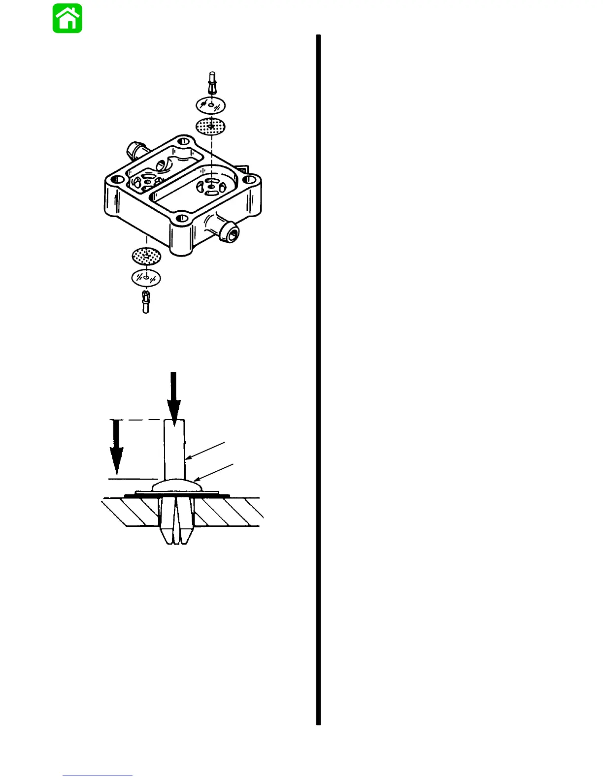
2. Install check valves and retainers into fuel pump
body.
51530
3. Reinstall rod into retainer cap and, use a small
hammer or hammer and punch to tap rod down
into retainer until flush with top of retainer.
a
b
a - Rod
b - Retainer Cap
Step-by-Step Reassembly
IMPORTANT: ALWAYS REPLACE GASKETS.
STEP-BY-STEP FUEL PUMP REASSEMBLY
After reassembling check valve in fuel pump body,
using the following procedure will help insure proper
reassembly:
1. Insert two 3 in. minimum length 1/4″ bolts (not the
fuel pump bolts) OR 1/4″ dowels, through the
opposite large holes (6mm bolt holes) in the
chamber plate, as locating dowels, and turn plate
upside down so that the inner side is facing up.
2. Insert coil spring and cap in place.
3. Place Boost Chamber GASKET over dowels
(bolts) and lower onto Chamber Plate -- BE SURE
that gasket directional alignment is correct and
that “V-tabs” are aligned.
4. Place Boost DIAPHRAGM over dowels, and
lower to assembly.
5. Place Fuel Pump Body over dowels, and lower to
assembly.
6. Insert Coil Spring and Cap in pump body.
7. Place Fuel Pump DIAPHRAGM over dowels, and
lower to assembly.
8. Place Pulse Chamber GASKET over dowels, and
lower to assembly.
9. Place Fuel Pump Base over dowels, and lower to
assembly.
10. Grasp assembly firmly and clamp together with
hands--turn over, and insert the 5mm Fuel Pump
BOLTS (hex-head); After tightening, remove
dowels (1/4″ bolts) used for locators.
11. Check that the directional alignment of all parts is
correct and that the “V-Tabs” are aligned.