Model WT3-201M Motorized Wire Crimp Pull Tester User’s Guide
8 PASS / FAIL LIMITS
8.1 General Information
Pass / fail limits are useful for tolerance checking with red and green indicators and audible tones.
Outputs are also provided, for triggering an external device such as an indicator or alarm in process
control applications. Two limits, high and low, are specified and stored in the non-volatile memory of the
tester and the primary reading is compared to these limits. The results of the comparisons are indicated
through the three outputs provided on the 15-pin connector, thus providing “under”, “in range”, and “over”
signaling.
8.2 Configuration
To configure pass/fail limits, select Pass / Fail Limits from the menu. The display appears as follows:
Either one, two, or none of the limits may be enabled.
The upper limit is displayed in the upper right corner of the display, and the lower limit is displayed in the
lower right corner, as shown in the Home Screen and Controls section. If only one limit has been
enabled, the word “OFF” appears in place of the other limit value. If neither limit has been enabled, the
upper and lower right corners of the display will be blank.
If the application only requires that a sample withstand a minimum specified force, set only the lower
pass/fail limit. If the value is below this limit, the lower red “X” illuminates. If the value is above this limit,
the green “checkmark” illuminates.
Note: Pass / fail limits and set point outputs reference the displayed reading, not necessarily the current
live load.
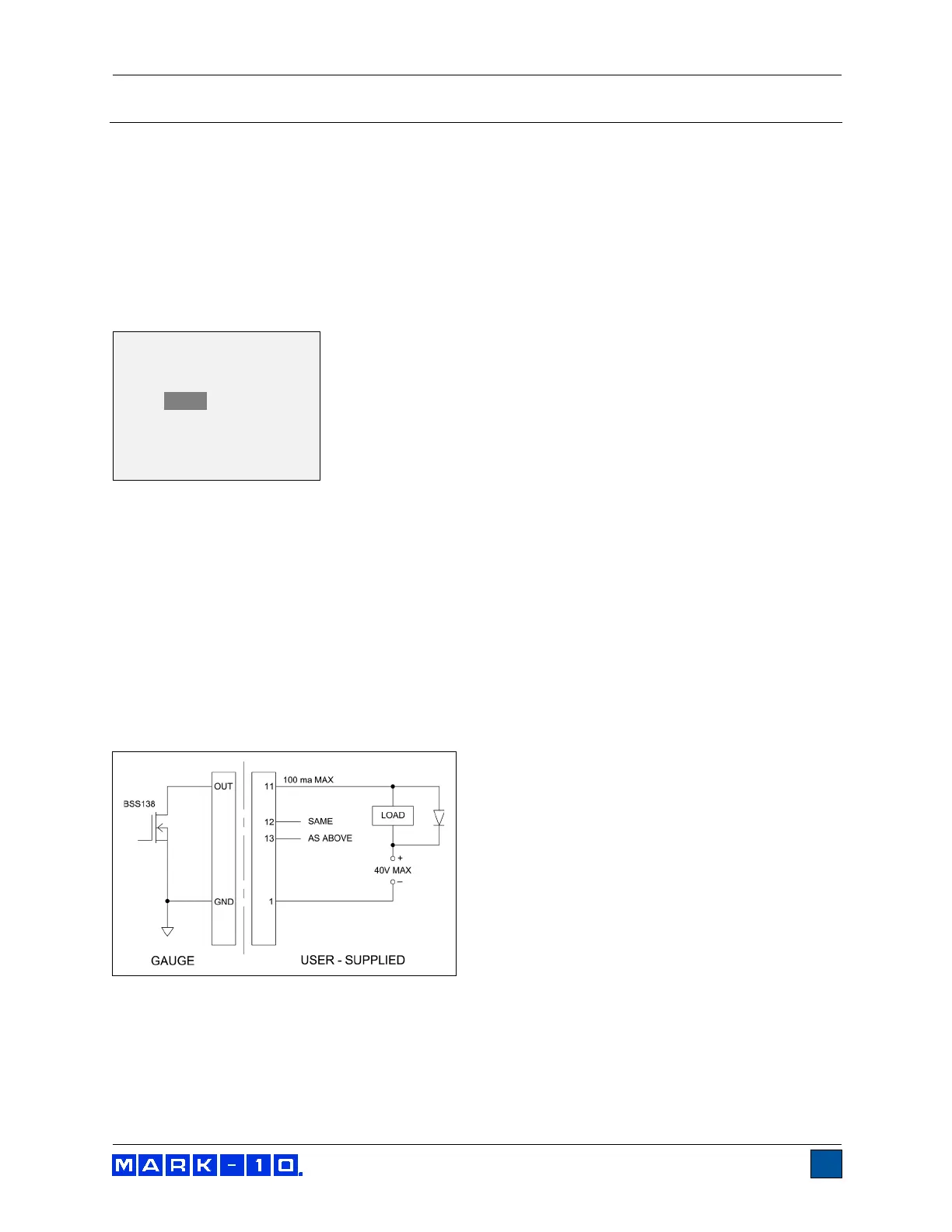
8.2.1 Set Point Outputs Schematic Diagram
Upper Disabled
* Upper Enabled
125.0
Lower Disabled
* Lower Enabled
122.5