Model WT3-201M Motorized Wire Crimp Pull Tester User’s Guide
18 COMMUNICATIONS AND OUTPUTS
Communication with the WT3-201M tester is achieved through the micro USB or 15-pin serial ports, as
shown in the illustration in the Power section. Communication is possible only when the tester is in the
main operating screen (i.e. not in a menu or configuration area).
18.1 Serial / USB
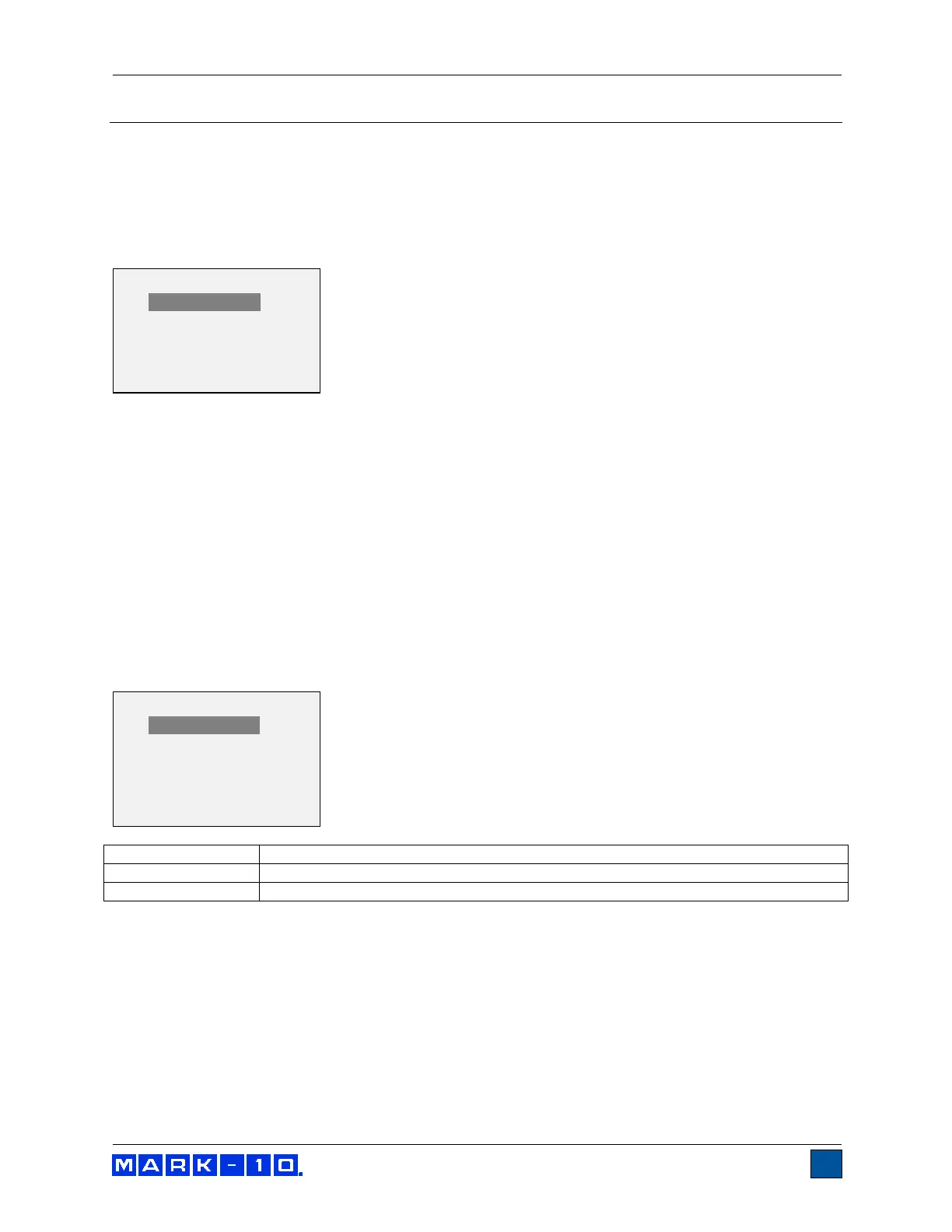
To set up RS-232 and USB communication, select Serial/USB Settings from the menu. The display
appears as follows:
Select either RS-232 or USB input (output is always simultaneous through both the USB and RS-232
ports). Communication settings are permanently set to the following:
Data Bits: 8
Stop Bits: 1
Parity: None
Other settings are configured as follows:
18.1.1 Baud Rate
Select the baud rate as required for the application. It must be set to the same value as the receiving
device.
18.1.2 Data Format
Select the desired data format. The display appears as follows:
Output format includes the value and unit of measure.
Output format includes the value only.
* Numeric + Units
Numeric Only
* RS232 Selected
USB Selected
+ Baud Rate
+ Data Format