Page 10
6 CONNECTING DIAGRAM
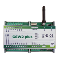
Before connection the GSW2 PLUS device please take a look at connection diagram.
Power supply – 12,0 -20,0V AC or
12,0 – 24,0V DC
Relay output 1 – Normal Close
Temperature sensor connector
Relay output 1 – Normal Open
USB for programming with PC
Relay output 2 – Normal Close
Relay output 2 – Normal Open
+12V DC AUX max. *100 mA in total !
Call Button 1 – is the same as IN1 !
GSM Intercom – Call point
(microphone & speaker) connections
Clamp for Backup Battery – (minus)
Clamp for Backup Battery + (plus)
*Do not use the 12V DC AUX power output for electric lock driving! You
can use it to power external sensors: Short-term current load (up to 1
minute) - up to 500mA; Long-term current load - up to 100mA! Use
separate power source for door electric lock!
Figure 1: GSW2 PLUS Connection diagram