Page 12
8 THE GSW2 PLUS PARAMETERS
To support versatile functionality of GSW2 PLUS different parameters are used. The parameters are
divided in logical sections and are described in the following chapters.
8.1 ALARM SUPPORT
Alarm reporting is supported by group of different parameters. First section is used to define the
relations needed for alarm to be trigged. The second section is used to report alarm.
8.1.1 ALARM TRIGGERING
Parameters are used to control (filter) the triggering of the alarm inputs.
8.1.1.1 IN parameters
Alarm and reset input can be triggered in 4 different ways. The status of the input can either be
normal closed (N.C) or normal open (N.O.) with positive (+ 12V) or negative (GND) voltage.
Activation of the input/alarm is reported by INx values 0 to 2. It the user needs to receive
information of the input/alarm restore use INx values 4 to 6. INx value 3 disables the input/alarm
reporting.
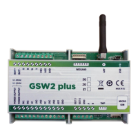
IN = 0 – Normal Open – triggered with negative voltage (GND)
IN = 1 – Normal Close – breaking negative or positive voltage loop
IN = 2 – Normal Open – triggered with positive voltage (+ 12V DC)
IN = 3 – Not in use
IN = 4 => IN = 0 + input reset SMS
IN = 5 => IN = 1 + input reset SMS
IN = 6 => IN = 2 + input reset SMS
+12V DC
INPUT 1-4
N.O.
contact
Figure 2: Input Connection diagram