Rad-97 Service Manual Chapter 5: Performance Verification Procedures
Masimo Corporation 61 www.masimo.com
9. To begin the overpressure test, press the Test button, then increase the pressure to the overpressure point:
• Increase pressure to approximately 130mmHg using the hand bulb.
• Very slowly increase the pressure as you approach the overpressure point.
• When the overpressure point is reached, the valves will open (a faint click can be heard when this occurs) and the pressure will rapidly reduce to 0mmHg. Be
sure to observe the pressure measurement on the manometer when the valves open.
10. Determine if the NIBP module passed the overpressure test:
• If the valves opened WITHIN the overpressure pass criteria, then the NIBP module PASSED the overpressure test for neonates. Go to step 11.
• If the valves opened BEYOND the overpressure point pass criteria, then press the Test button again to confirm the overpressure point. If the valves open
repetitively beyond the pass criteria,contact Masimo Technical Services. See Contacting Masimo on page 65.
11. To stop testing, press Stop.
12. Disconnect the manometer, 500mL bottle or cuff wrapped around solid object, and hand bulb from the NIBP module.
13. Power OFF the manometer.
NomoLine® Capnography Verification
Follow the verification procedures provided in:
• 301554/LAB-10824 - Service Manual, NomoLine ISA Maintenance Kit, English, Global
Alarm Limit Test
Alarm Limit Test
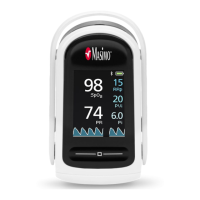
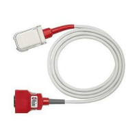
1. Connect a sensor to the Rad-97. Place the sensor on a finger to obtain an SpO
2
value.
2. Change the High SpO
2
Alarm parameter to a value two points below the currently selected value. Refer to the Operator's Manual for Rad-97 for complete
information.
3. Verify that the newly set parameter is shown on the Display screen.
4. Return the parameter to its original setting.
5. Repeat steps 1 to 3 for all active parameters.
6. Reset the alarm limits again to the original settings.
Nurse Call Setting Connections
For maximum flexibility, either normally open or normally closed signals are available. During an alarm condition or a low Signal IQ event, depending on the configuration of
the device output, the normally open pin will be connected to the common pin, and the normally closed pin will be disconnected. In addition, the Nurse Call Polarity can be
inverted to accommodate various nurse call station requirements. See Device Output.
Only authorized service personnel should connect one of these two signals to a hospital’s Nurse Call system.
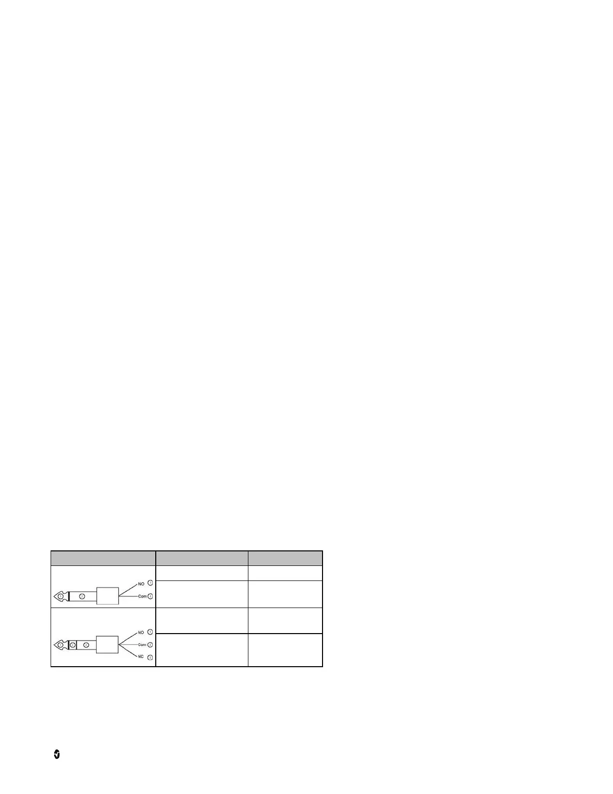
Cable Type Nurse Call Event Menu Setting
2-Circuit
2 contacts normally opened Nurse Call Polarity Normal
2 contacts normally closed Nurse Call Polarity Inverse
3-Circuit
1 and 2 contacts normally opened
2 and 3 contacts normally closed
Nurse Call Polarity Normal
1 and 2 contacts normally closed
2 and 3 contacts normally opened
Nurse Call Polarity Inverse