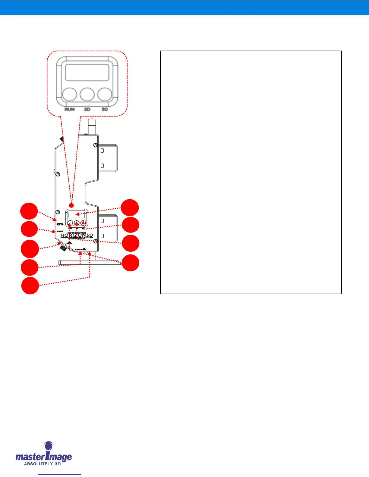
3. Side Panel | Switch & Port
J. DIP switch: To change Sync polarity (True or Invert) & 3D
Position (UP or DOWN).
K. Ethernet Port: Used for Automation, Alignment, Monitor
Program & Firmware Upgrade of Control Panel.
L. GPIO/TTL Port: Connected between HORIZON3D and DLP
Projector for 3D SYNC Input and automation function.
M. Actuator Port: Connected between Control Panel and lift-column
actuator to move the Optical Head between 3D position or 2D
position.
N. DC Port: DC (+24V) Power Port.
(*Note: If the Actuator Cable is connected to the Actuator port, do
not connect the DC power adaptor to the Control Panel, connect to
the Lifting Column)
O. 7-Segment LED: Used for Sync Frequency or Error Codes display.
P. 3D Button: Used to move the Optical Head to 3D position and to
activate 3D operation.
Q. 2D Button: Used to move the Optical Head to 2D position and to
stop 3D operation.
R. RUN Button: Activates 3D operation.