Installation & Operation Manual | HORIZON3D
5.2. Head Assembly – Component Identification
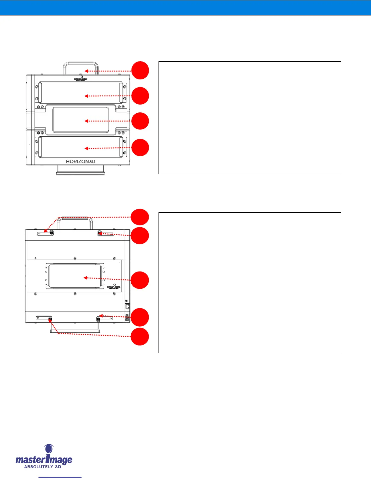
1. Front Panel
A. Handle: Enables lifting or hand-carrying the Optical Head.
B. Upper Half Image Outflow: Composed of the upper LCD
and thick plate (Optional, To improve the alignment of the
upper half image if required).
C. Central Full Image Outflow: Composed of the central
LCD.
D. Lower Half Image Outflow: Composed of the lower LCD
and thick plate (Optional, To improve the alignment of the
lower half image if required)
2. Back Panel
E. Upper Vertical Alignment: Used to align the vertical offset of
the upper half reflected image (Operated manually or remotely).
F. Upper Horizontal Alignment: Used to align the horizontal
offset of the upper half reflected image (Operated manually or
remotely).
G. Lower Vertical Alignment: Used to align the vertical offset of
the lower half reflected image (Operated manually or remotely).
H. Lower Horizontal Alignment: Used to align the horizontal
offset of the lower half reflected image (Operated manually or
remotely).
I. Entrance Window: Entrance Window of 3D Image from DLP
projector.