Installation & Operation Manual | MI-WAVE3D
6.3.3. Connect the Actuator Cables
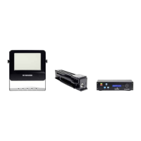
Connect the GPIO Sync Cable and DC
Adaptor Cable to the end of the Actuator.
(Figure 9).
Figure 9. Height and Angle Adjustment
Screws
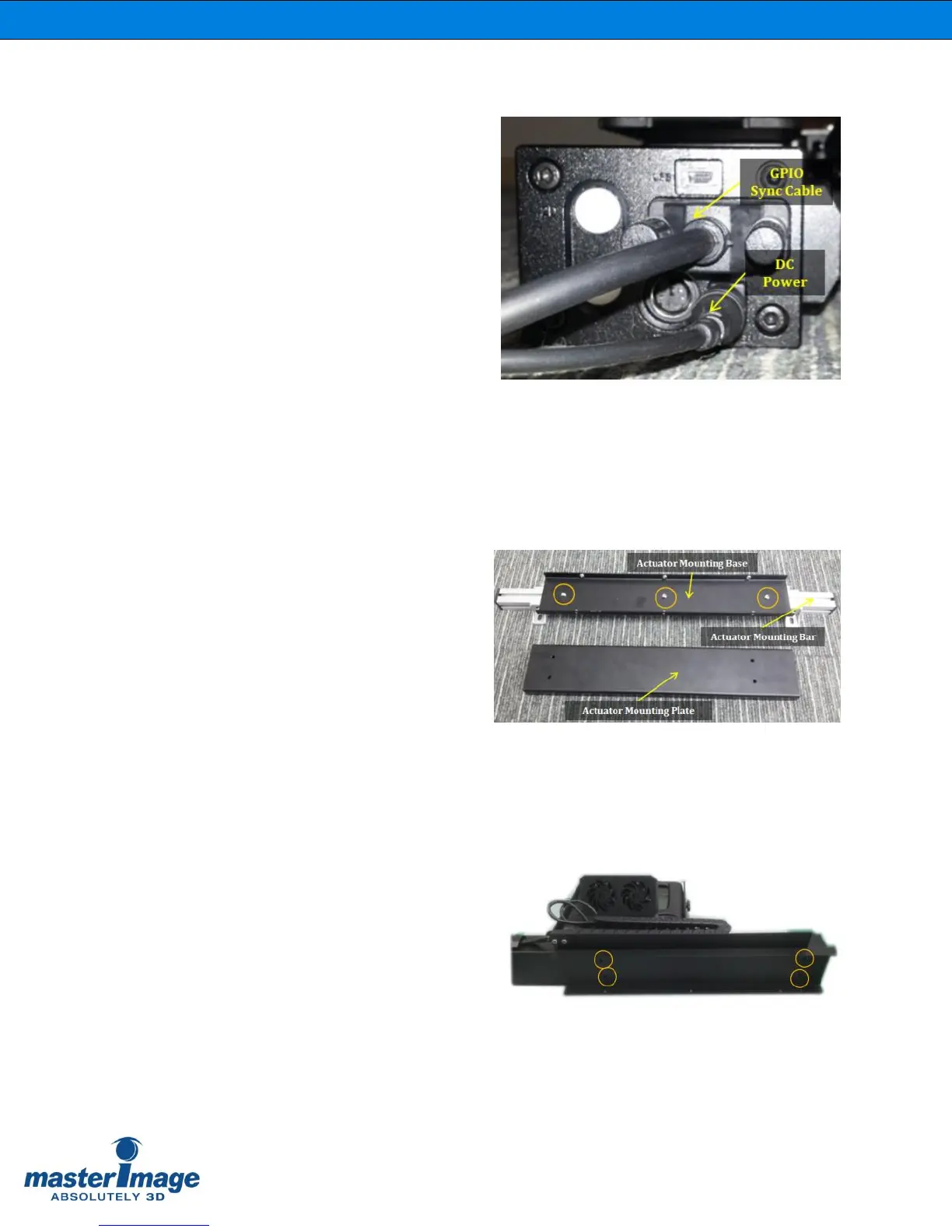
6.3.4. Attach the Actuator Mounting Base
Mount the actuator mounting base to the
actuator mounting bar with 3 supplied
screws. (Figure 10).
Figure 10. Actuator Mounting Base
6.3.5. Attach the Actuator Mounting Plate
Fix the actuator mounting plate on the
bottom of the actuator with 4 supplied
screws. (Figure 11).
Figure 11. Actuator Mounting Plate