Vision System Manual
149
Matrix
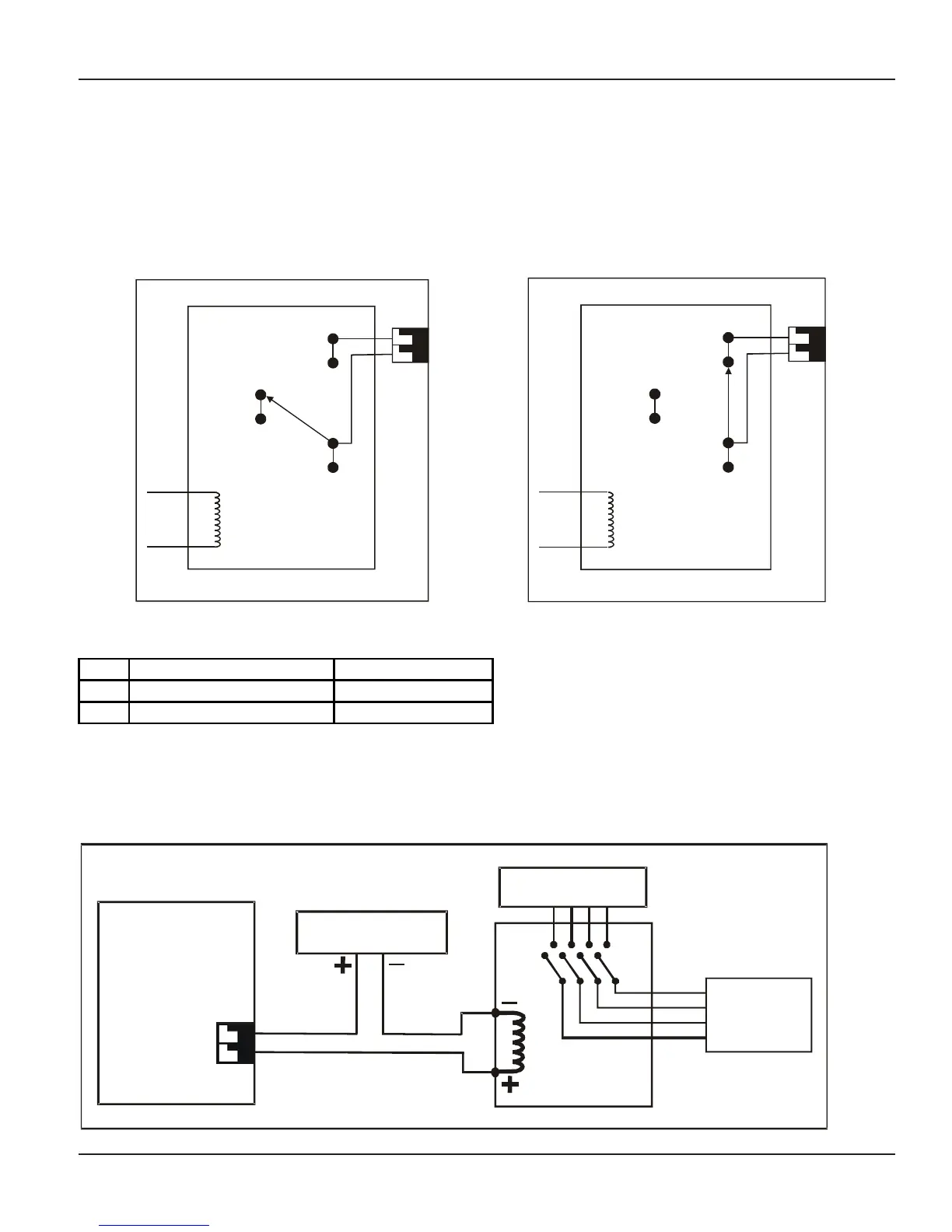
throw relay (SPDT). As shown in the figure in normal condition the contact terminal (pole) of the relay rests
on ‘NO’ terminal (If relay port is programmed as active high.), which is NC (not connected to any other part of
circuit). When the user issues a command to turn ON the relay, the coil of this relay gets energized, which
throws the contact terminal (pole) of the relay to ‘NC’ terminal. This closes the path as shown in figure 2 and
turn ON the device connected to it or energized the coil of the contactor, as the case may be. When the user
issues a command to turn OFF the relay, the coil gets de-energized which throws the contact terminal to `NO’
position. This opens the circuit path, which in turn, turns OFF the device connected to it.
Figures shown below depicts the operation of Relay Port:
From
Control
Circuit
NO
NC
Pole
Vision
Figure 1: Switch OFF condition
Relay Port
Figure 2: Switch ON condition
From
Control
Circuit
NO
NC
Pole
Vision
Relay Port
How to use it?
1 Lift the handset. Dial tone
2
Dial
3990
(Relay OFF).
Confirmation tone
3
Dial
3991
(Relay ON).
Confirmation tone
The above commands are applicable only when relay port is programmed for any of the mode. Total manual,
duration based Auto OFF, Duration based Auto ON, time based Auto ON, Time based Auto OFF.
How to connect external devices to relay port?
A 3-Phase load can be connected to the Relay Port as shown below:
DOP
AC Mains
RBYN
R
B
Y
N
Vision
Load
60VDC Max.