38
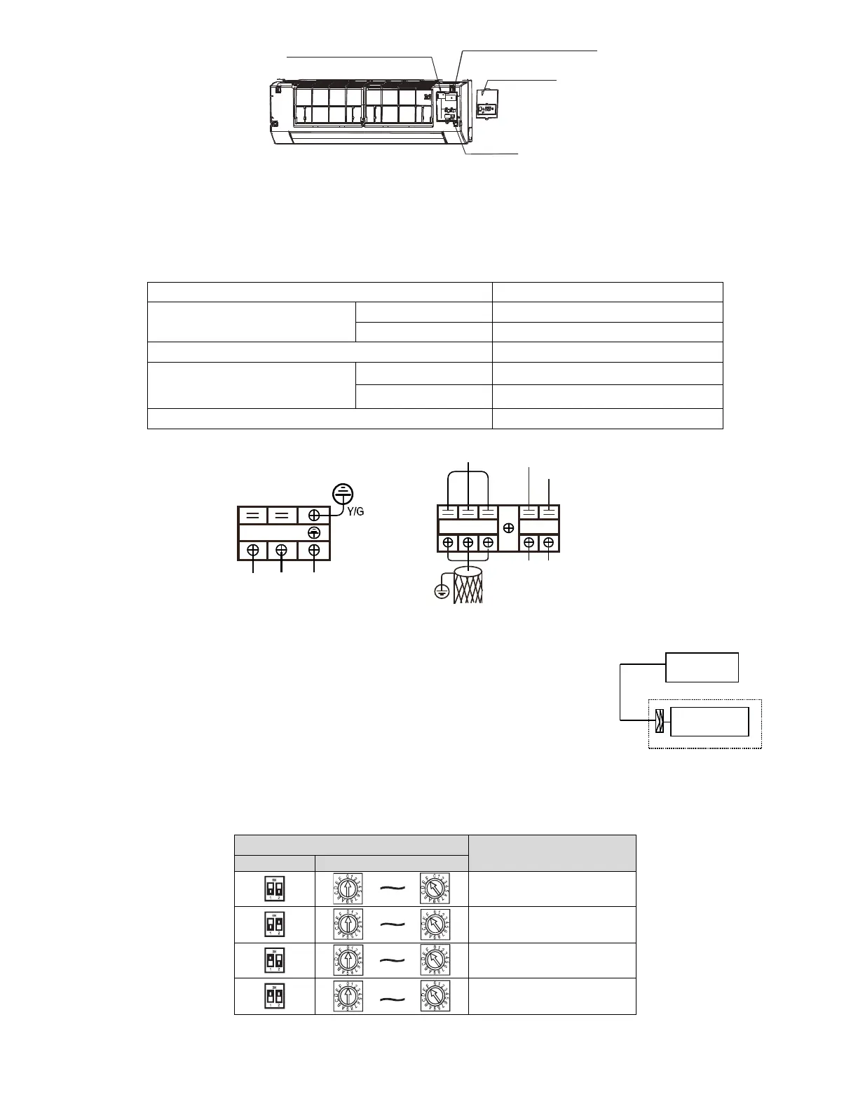
The wire holder of pwer cord
(three-position)
The wire holder of signal line
(five position)
E-part box
cover plate
Dial switch
8.7.1 Terminal Board Diagram
Please refer to the indoor unit wiring diagram for the wiring.
NOTE: The air-conditioners can connect with Central Control Monitor (CCM). Before operation, please wiring correctly and
set system address and network address of indoor units.
■ Power supply specifications
Power supply
Indoor unit power wiring (mm²)
Below 20m
Twisted pairwire 2.5 mm²
Below 50m Twisted pairwire 6 mm²
2
The power cord type designation is H05RN-F or above.
EYX
White
White
Blue
TO CCM. COMM.BUS
21
Black
XT2
Water pump
Gray
NL
POWER IN
XT1
- Please adopt the shielded twisted-pair wire, and connect the shielded layer to E.
The reserved wire control function is indicated in broken line table, users can
purchase the wire controller when necessary.
WIRE CONTROLLER
To wire controller
DISPLAY BOARD
8.7.2 Network address setting
Every air-conditioner in network has only one network address to distinguish each other. Address code of air-conditioner in
LAN is set by code switch on Network Interface Module (NIM), and the set range is 0-63.
Network address code
00 ~ 15
16 ~ 31
32 ~ 47
48 ~ 63