11921 Slauson Ave. Santa Fe Springs, CA. 90670 (800) 227-4116 FAX (888) 771-7713
19
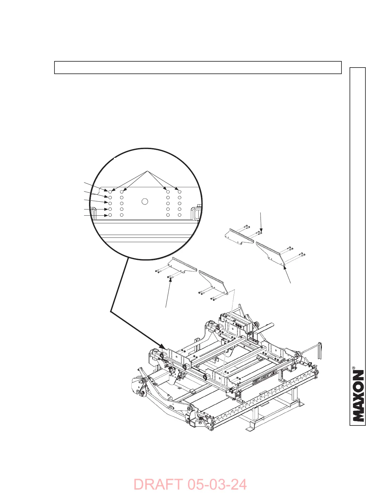
INSTALLATION
PLATE
(4 PLACES)
NOTE:
Installation brackets are located on both sides of Liftgate in 4 places..
INITIAL MOUNTING ADJUSTMENTS BASED ON BED HEIGHT
INSTALLATION PLATES FOR TRAILERS
WITH 48” SLIDE RAILS
FIG. 19-1
2. Unbolt and remove installation plates from Liftgate (FIG. 19-1). Measure and record
trailer fl oor height (BH), fl oor thickness (H) and rear sill (RS).
Refer to TABLES 17-1 or 18-1.
FIG. 19-1A
MOUNTING HOLES
(TABLE 17-1)
HOLE #1
HOLE #2
HOLE #3
HOLE #4
HOLE #5
3. Bolt installation plates to Liftgate (FIGS. 19-1 and 19-1A, or FIGS. 20-1 and 20-1A).
Use mounting holes listed in TABLES 17-1 or 18-1, according to the dimensions re-
corded in Instruction 2 for BH, H and RS. Torque mounting bolts to 100 lb-ft.
HEX BOLT, 1/2”-13,
1-3/4” LG.
(16 PLACES)
FLANGE NUT, 1/2”-13
(16 PLACES)
1. Remove shipping bands from liftgate and installation jig.
STEP 1 - INSTALLING LIFTGATE ON TRAILERS
 Loading...


