11921 Slauson Ave. Santa Fe Springs, CA. 90670 (800) 227-4116 FAX (888) 771-7713
44
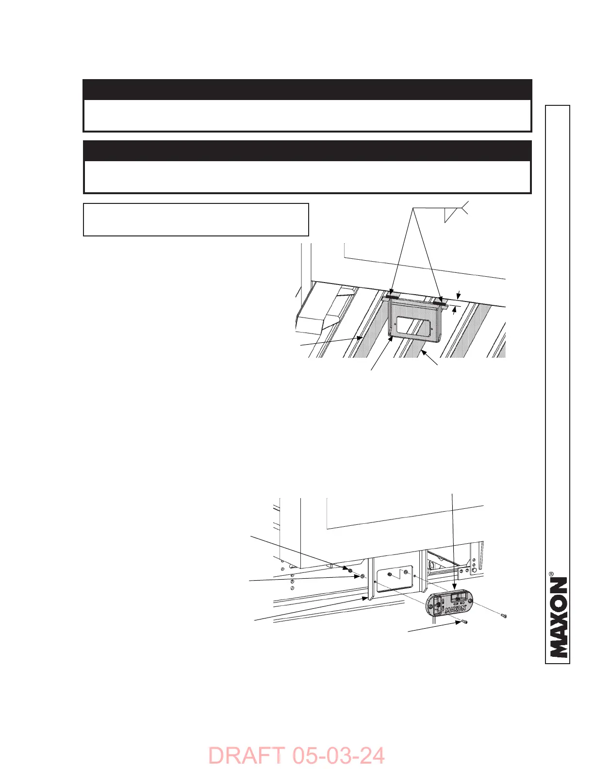
STEP 3 - ATTACH CONTROL SWITCHES
2 WELDS MIN.
3/16”
1. Position and weld bracket for
external control switch (Kit item)
to vehicle crossmembers near
rear sill on curb side of vehicle
(FIG. 44-1).
Prevent damage to control box. Make sure installed control box does not
protrude from the vehicle body.
CAUTION
CAUTION
To protect the original paint system, a 3” wide area of paint must be removed
from bracket on all sides of the weld area before welding.
CONTROL BRACKET WELDED TO CROSSMEMBERS
FIG. 44-1
EXTERNAL CONTROL
BRACKET
CROSSMEMBER
1”- 2”
2. Fasten external main control
switch to bracket using fl at-
washers and lock nuts (Kit
items) as shown in FIG. 44-2.
FASTENING MAIN CONTROL TO BRACKET
FIG. 44-2
EXTERNAL
CONTROL SWITCH
EXTERNAL-
MAIN CONTROL
BRACKET
BUTTON SCREW,
1/4”-20 X 1”
(2 PLACES)
FLAT WASHER, 1/4”
(2 PLACES)
LOCK NUT,
1/4”-20
(2 PLACES)
CROSSMEMBER
NOTE: Grind galvanized surface material
from areas to be welded.
 Loading...


