11921 Slauson Ave. Santa Fe Springs, CA. 90670 (800) 227-4116 FAX (888) 771-7713
43
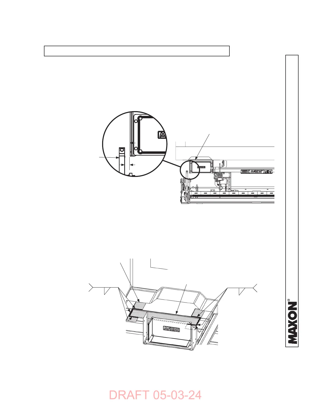
4. Clamp J-box mounting bracket in correct position on
mounting fl ats (FIG. 43-1). Prior to welding, check
the clearance between J-box and lift arm in both
fl oor-level and ground-level positions (FIGS. 43-1
and 43-1A). Ensure 1/2” clearance between the lift
arm and the J-box bracket (FIG. 43-1A).
WELDING J-BOX MOUNTING BRACKET
FIG. 43-2
5. Weld J-box mounting bracket in correct
position on fl ats (FIG. 43-2).
J-BOX
MOUNTING BRACKET
1/4”
3 PLACES
1/4”
POSITIONING J-BOX MOUNTING BRACKET
FIG. 43-1
1/2”
LIFT ARM
FIG. 43-1A
J-BOX
MOUNTING BRACKET
MOUNTING FLAT
(2 PLACES)
3 PLACES
STEP 2 - WELD J-BOX TO UNDERBODY - Continued
NOTE: Grind galvanized surface material from areas to be welded.
 Loading...


