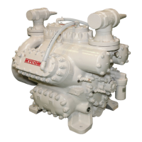
Reciprocating Compressor M Series
x
5.5.8 Crankshaft............................................................................................................ 5-31
5.5.8.1 Removing the Crankshaft .......................................................................... 5-32
5.5.8.2 Assembly of the Thrust Roller Bearing (Shaft Side) .................................. 5-33
5.5.8.3 Assembly of the Crankshaft....................................................................... 5-34
5.5.9 Bearing Head ....................................................................................................... 5-35
5.5.9.1 Removing the Bearing Head ..................................................................... 5-36
5.5.9.2 Replacing the Main Bushing (Bearing Head Side) .................................... 5-36
5.5.9.3 Assembly of the Thrust Roller Bearing (Bearing Head Side) .................... 5-36
5.5.9.4 Assembly of the Bearing Head .................................................................. 5-37
5.5.10 Dis charge Va lve Cage As sembly ........................................................................ 5-38
5.5.10.1 Assembly of the Discharge Valve Spring ................................................... 5-38
5.5.11 Piston Assembly ........................................................................................ 5-39
5.5.11.1 Assembly of the Connecting Rod Bushing ................................................ 5-39
5.5.11.2 Assembly of the Piston Rings .................................................................... 5-40
5.5.12 Cylinder Sleeve Assembly ................................................................................... 5-41
5.5.12.1 Assembly of the Cam Ring ........................................................................ 5-41
5.5.13 Seal Cover Assembly .......................................................................................... 5-42
5.5.13.1 Removing the Shower Flushing Sleeve .................................................... 5-42
5.5.13.2 Assembly of the Mechanical Seal Mating Ring ......................................... 5-43
5.5.13.3 Assembly of the Bellows Oil Sleeve .......................................................... 5-43
5.5.14 Main Bearing Head Assembly ............................................................................. 5-44
5.5.14.1 Replacing the Main Bushing (Pump Side)................................................. 5-44
5.5.14.2 Assembly of the Thrust Washer (Pump Side) ........................................... 5-44
5.5.15 Oil Fi lter Ass embly ............................................................................................... 5-45
6 Troubleshooting
6.1 Troubleshooting Table ............................................................................... 6-1
7 Related Document
7.1 Development View and Configuration Table of the Parts ........................ 7-1
7.2 List of Tightening Torques for Bolts and Nuts ....................................... 7-11
7.3 List of Tools for Disassembly .................................................................. 7-12
7.4 Vibration and Sound Data ........................................................................ 7-14
7.4.1 Vibration ............................................................................................................... 7-14
7.4.2 Sound Data .......................................................................................................... 7-15
7.5 Oil Cooler Heat Rejection
(OHR)/Head Jacket Heat Rejection (JHR) (N4M, N6M, N8M) .................. 7-16
7.6 Starting Torque ......................................................................................... 7-25
7.7 Parts Inspection and Replacement Standards ....................................... 7-28


 To Next Page