Overview
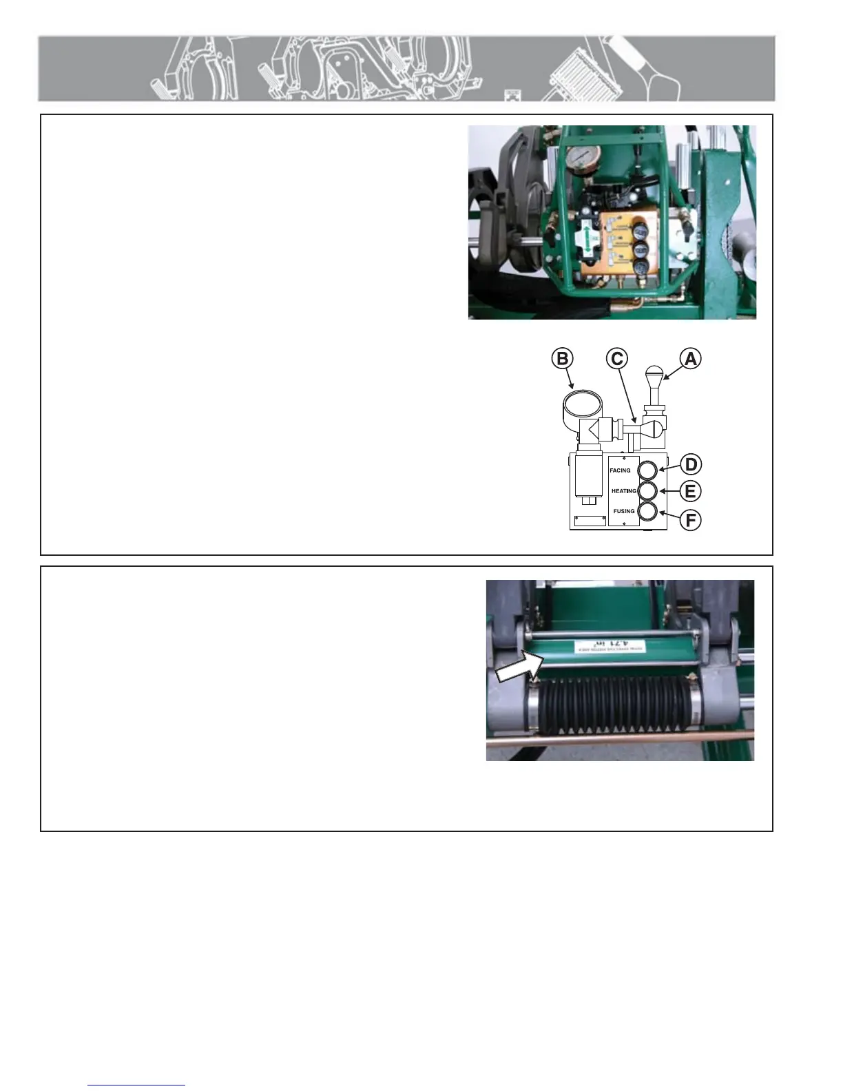
Hydraulic Manifold Block
Mounted on this block are a carriage directional control valve, a
pressure reducing selector valve, three pressure reducing valves,
and a 1500 psi gauge.
A) The carriage control valve, mounted on the top of the
manifold, determines whether the carriage is moving left, right,
or is in neutral.
B) A 1500 psi gauge is mounted on top of the manifold.
C) The selector valve, mounted on the front of the manifold,
selects a reduced pressure from one of the pressure reducing
valves.
Each pressure reducing valve is labeled with a different function:
D) The top valve adjusts facing pressure to a maximum of 400
psi.
E) The middle valve adjusts heating pressure to a maximum of
400 psi.
F) The bottom valve adjusts fusion pressure to a maximum of
1500 psi.
TX02133-07-08-03
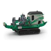
Hydraulic Cylinders
The two carriage cylinders have air bleed screws and must be
bled if the system ever runs low on oil or leaks air on inlet side
of pump. Air in the system is indicated when carriage movement
becomes jerky and erratic.
Consult the "Maintenance" section of this manual for procedure to
follow when bleeding air from system.
TX01137-10-23-96
PH02489-07-08-03
PH02490-07-08-03
CD00138A-9-12-94
2 - 5