Overview
Hydraulic Fluid Reservoir
The reservoir is incorporated in the HPU. The fluid level is read
from a dipstick and has a notch to indicate the proper fluid level.
Never allow dirt or other foreign matter to enter the open tank.
Refer to the "Hydraulic Fluids" section of this manual for hydraulic
fluid recommendations.
TX04662-03-24-14
PH04144-4-12-10
2 - 3
DynaMc EP Hydraulic Power Unit (HPU)
The DynaMc EP HPU consists of three main hydraulic components:
1. Power pack - Consists of a capacitor start electric motor and
gear pump that are submerged in the fluid reservoir to aid in
cooling and reduce noise.
2. Hydraulic accumulator - Allows the power pack to cycle
on and off to meet the demands of the hydraulic system, which
reduces noise and power consumption.
3. Carriage manifold assembly - Standard McElroy design for
familiar operation and common service parts with other McElroy
equipment.
There are two pressure gauges on the HPU. The pressure gauge
above the carriage directional valve displays fusion pressure. The
pressure gauge on the rear left side of the HPU displays main
system pressure, which will fluctuate between approximately 1600
psi - 2900 psi as the power pack cycles on and off.
The main power switch for the HPU is located on the front side of
the electrical box. Next to the power switch is a digital volt meter
that displays incoming voltage to the HPU. On the bottom side of
the electrical box is a motor circuit breaker.
Electric motors are not explosion proof. Operation
of these components in an explosive atmosphere
will result in serious injury or death.
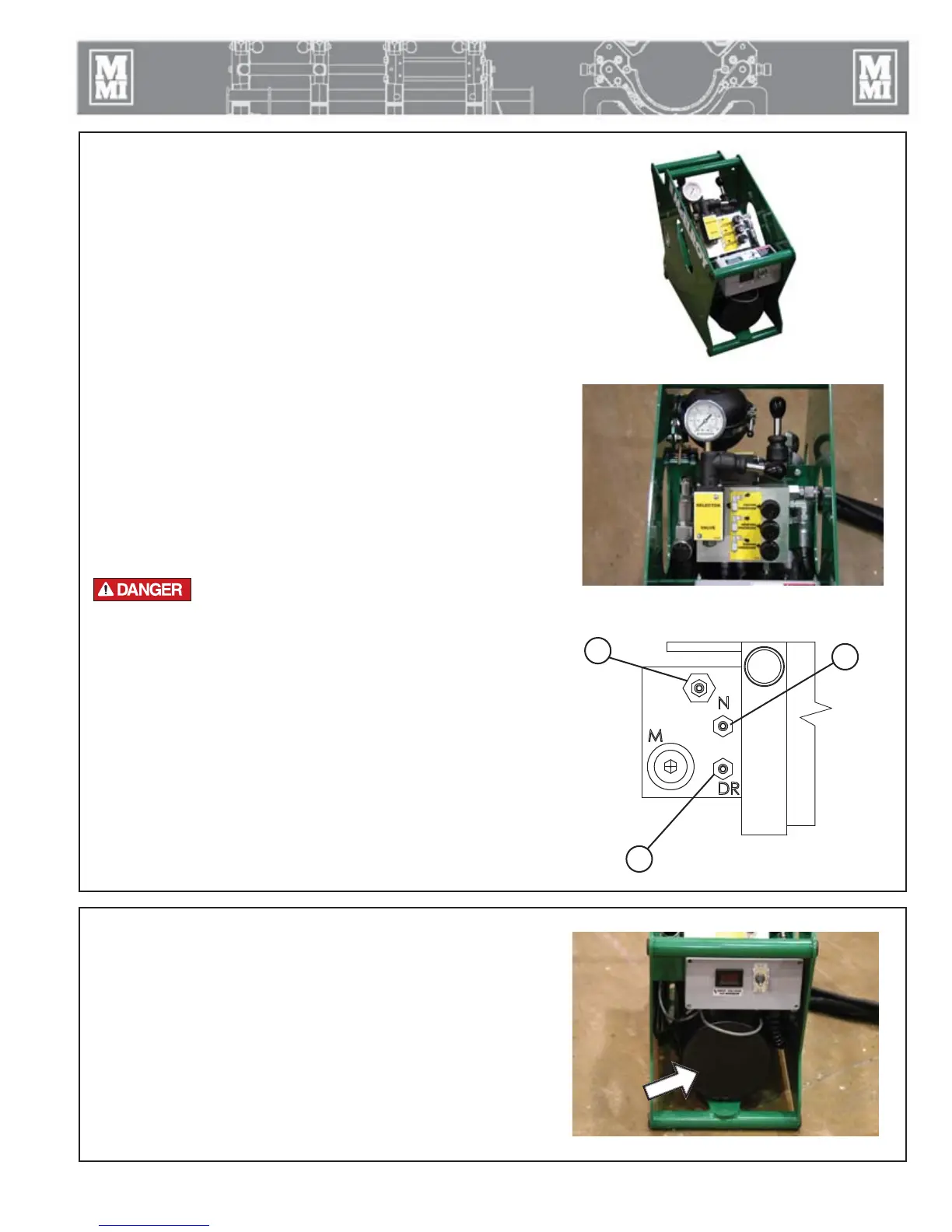
Power Pack Manifold Block
The DynaMc EP HPU's power pack has three factory preset valve
adjustments:
1. Valve "N" is adjusted completely in (clockwise).
2. Valve "DR" is adjusted completely out (counter-clockwise).
3. The non-labeled valve is the main system pressure relief valve that
protects against over-pressurization.
NOTICE: These valves are properly set at McElroy and should never be
re-adjusted.
TX04661-10-5-15
PH04146-4-12-10
PH04142-4-12-10CD00831-10-5-15
1
2
3