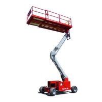
Page 157 Speed Level Series - Service & Parts Manual
January 2019Section 9 - Troubleshooting - 3084ES Models
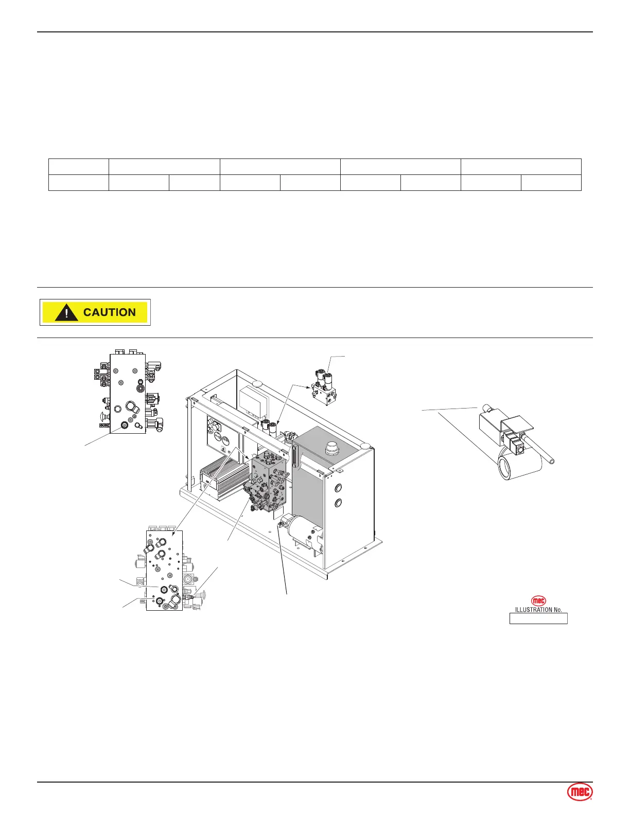
Hydraulic Pressure Adjustment - 3084ES
Before attempting to check and/or adjust pressure relief valves, operate the machine for 15 minutes
or long enough to sufficiently warm the hydraulic fluid.
Insert a 0-5000 psi gauge onto the pressure test port on the valve manifold using gauge adapter
fitting MEC part no. 8434
Model Main Lift Steer Stand-By
3084ES 2800 PSI 193 bar 2500 PSI 172.4 bar 2000 PSI 137.9 bar Not Used Not Used
Adjusting Relief Valves
Remove the tamper proof cap.
Turn adjustment screw “IN” to increase pressure.
Turn adjustment screw “OUT” to decrease pressure.
When correct pressure is obtained replace tamper proof cap with a new one.
Do not operate pump with tamper proof cap removed. Fluid will emit
under pressure.
ART_3160
15 AMP
BREAKER
RV1
Lift Relief
RV2
Steer Relief
RV7
Main Relief
Alternate Configuration
RV4
Overpressure
Relief
LEFT SIDE
FRONT
LIFT CYLINDER
MANIFOLD
Gauge Port
(Test Port)
Hydraulic
Pump
RV7
Main Relief
Back of Manifold
Adjustments - 3084ES
The Hydraulic Pump used in this model is not adjustable.
See Section 11 - Schematics for correct pressure settings.
Main Relief (RV7)
Disconnect forward or reverse coil of drive valve.
Energize drive function by moving joystick in the direction of the already disconnected coil.
•
•
•
•
•
•