Do you have a question about the Mec Speed Level Series and is the answer not in the manual?
Instructions for maintaining MEC aerial work platforms, including adjustments and repairs.
Guidelines for safe operation and modifications of MEC aerial work platforms.
Explanation of safety symbols, colors, and general maintenance tips for aerial work platforms.
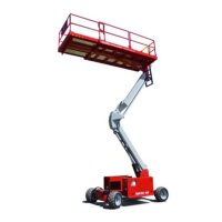
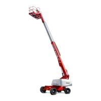
Technical specifications for RT models, including dimensions, capacity, and performance.
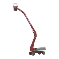
Technical specifications for ES models, covering dimensions, capacity, and performance.
Crucial safety advice for operating and servicing the machine, emphasizing proper support and component care.
Information on the hydraulic system, warning about high-pressure fluid hazards and leak correction.
Precautions for preventing damage to the battery and electrical system, including cable connection order.
Torque values for American Standard cap screws based on SAE grade and size.
Torque values for metric cap screws based on grade and size.
Torque specifications for hydraulic components like cartridge poppets, fittings, and hoses.
Procedures for emergency stop, selector switch use, and emergency lowering in case of power failure.
Safety precautions and procedures for lifting and supporting the machine using jacks and jack stands.
Overview of the hydraulic integrated circuit, its load-sensing feedback type, and pump operation.
Explanation of the hydraulic system's components and their functions, including reservoir, pump, manifold, and drive/brake system.
Precautions for handling hydraulic fluid and recommendations for fluid types and system flushing procedures.
Procedures for removing and installing the hydraulic pump on 3084RT models, including torque specifications.
Procedures for hydraulic manifold removal, disassembly, cleaning, assembly, and installation.
Details on the hydraulic drive system and dynamic braking circuit, including housing and shaft disassembly/assembly.
Explanation of the steering system, comprising wheel motors, cylinders, and control valves, and its hydraulic linkage.
Description of the platform leveling system, its hydraulic cylinders, pivot mount, and GP400 processor control.
Details on the platform lift circuit for 3084RT and 3084ES models, including single-use speed lowering and holding valve operation.
Overview of the electrical control system, including lower and upper controls, and emergency stop functionality.
Safety precautions for handling batteries, their types in 3084RT and 3084ES models, and maintenance procedures.
Step-by-step instructions for removing and installing batteries, emphasizing safety precautions.
Labeled diagram of lower controls for 3084RT models, with a description of each control's function.
Labeled diagram of upper controls for 3084RT models, with a description of each control's function.
Explanation of movement alarm, EZFit angle sensor, and pressure transducer functions for system monitoring.
Procedures for performing continuity checks on selector and toggle switches using an ohm meter.
Location of GP400 control module components and diagnostic information sources.
Procedure for GP400 calibration using the EZ-Cal tool, including angle and pressure sensor calibration.
Descriptions of failure messages (F codes) encountered during calibration and their potential causes and solutions.
General tips for troubleshooting hydraulic pump and electrical system malfunctions, covering common causes and notes.
Overview of the 3084RT electronic control system, its modules, and protection features.
Description of the GP400 module's role as the system's brain, its inputs/outputs, and EZ-Cal scan tool usage.
Explanation of the Matrix Module and Terminal Block Module (TBM) functions in relaying operator inputs and providing circuit connections.
Information on the EZ-Cal handheld scan tool, its interface capabilities, and system power-up requirements.
Procedures for adjusting machine personalities using the EZ-Cal in Access Level 1, with factory settings and explanations.
Procedures for using the EZ-Cal Diagnostics menu to view and test individual circuits, comparing ID numbers with flow charts.
A guide to help technicians identify problem areas based on symptoms and provides potential causes and solutions.
Troubleshooting tips for hydraulic fluid pump and battery charge state in 3084ES models, covering common electrical and hydraulic issues.
Overview of the 3084ES electronic control system, its modules, and protection features.
Description of the GP400 module's role, its inputs/outputs, and usage with the EZ-Cal scan tool.
Information on the EZ-Cal handheld scan tool, its interface capabilities, and system power-up requirements.
Procedures for adjusting machine personalities using the EZ-Cal in Access Level 1, with factory settings and explanations.
Procedures for using the EZ-Cal Diagnostics menu to view and test individual circuits, comparing ID numbers with flow charts.
A guide to help technicians identify problem areas based on symptoms and provides potential causes and solutions.
Hydraulic schematic diagram for 3084RT models, illustrating fluid flow and component connections.
Hydraulic schematic diagram for 3084ES electric models, illustrating fluid flow and component connections.
Electric schematic diagram for the upper controls of 3084RT models, showing wiring and component connections.
Electric schematic diagram for the upper controls of 3084ES models, showing wiring and component connections.
Base electric schematic for 3084RT Dual Fuel models, detailing engine, generator, and control connections.
Base electric schematic for 3084ES models, detailing engine, generator, and control connections.
Illustrated breakdown of early style upper controls for ANSI models, showing component placement and numbering.
Illustrated breakdown of lower controls for 3084ES electric models, showing component placement and numbering.
Illustrated breakdown of lower controls for 3084RT Dual Fuel models, showing component placement and numbering.
Illustrated breakdown of lower controls for 3084RT Diesel models, showing component placement and numbering.
Instructions for platform installation for models up to serial #11800046, including top and side-bolted ladder types.
Illustrated breakdown of platform and rails for 3084 models up to serial #11800046.
Illustrated breakdown of platform and rails components for 2684 models, Part 1.
Illustrated breakdown of platform and rails components for 2684 models, Part 2.
Illustrated breakdown of the boom mount and pivot assembly, showing pins, bolts, and bearings.
Illustrated breakdown of the chassis planetary drive assembly, showing motors, mounting components, and fasteners.
Illustrated breakdown of the lower boom assembly, showing weldments, pins, bolts, and cylinders.
Illustrated breakdown of the upper boom assembly, showing pins, bolts, washers, and guards.
Illustrated breakdown of the front axle assembly, showing motors, cylinders, and mounting hardware.
Illustrated steps for installing the front axle assembly, showing component placement and fastener locations.
Illustrated steps for installing the rear axle assembly, showing hydraulic motors, drive ports, and brake components.
Exploded view illustration of the rear wheel motor components, including endcover, piston, and seals.
Exploded view illustration of the front wheel motor components, including endcover, piston, and seals.
Illustrated breakdown of the main manifold assembly for electric models, showing component locations on left, front, right, and back views.
Illustrated breakdown of the main manifold assembly for RT models, showing component locations on front, left, right, and back views.
Illustrated breakdown of the leveling manifold assembly, showing components on front, bottom, left, and right views.
Illustrated breakdown of the RT manifold assembly, showing component locations on front, left, right, and back views.
Diagram illustrating hydraulic hose routing for RT models, covering steer, brake, and case drain systems.
Diagram illustrating hydraulic hose routing for RT models, covering lift and pump systems, including manifold connections.
Diagram illustrating hydraulic hose routing for ES models, covering platform level and axle float systems.
Diagram illustrating hydraulic hose routing for ES models, covering drive motors and manifold connections.
Diagram illustrating hydraulic hose routing for ES models, covering lift and pump systems, including manifold connections.
Illustrated breakdown of the lift cylinder, showing seals, piston, and mounting hardware.
Illustrated breakdown of the steering cylinder, showing seals, piston, and rod components.
Illustrated breakdown of the level cylinder, showing components and connections.
Illustrated breakdown of the axle lock cylinder, showing seals, pins, and fittings.
Illustrated steps for installing control and power modules, showing mounting brackets and fasteners.
Illustrated breakdown of the ES control module, drawing 1 of 2, showing component placement and numbering.
Illustrated breakdown of the ES power module, showing batteries, charger, and control components.
Illustrated breakdown of the RT power module, showing generator, control module, and engine components.
Illustrated breakdown of the Diesel power module assembly, showing engine, radiator, and fuel tank components.
Illustrated breakdown of the dual fuel engine mount, showing engine, radiator, and fuel filter components.
Illustrated breakdown of the Diesel engine mount, showing engine components, relays, and fuel system parts.
Illustrated breakdown of the LP tank assembly for dual fuel models, showing fittings and mounting hardware.
Illustrated breakdown of the generator option for older RT models, showing control module and upper controls.
Diagram illustrating wire harness routing for electric models, showing connections between control modules and components.
Diagram illustrating wire harness routing for RT models, showing connections between control modules and components.
Illustrated identification of decals for ES models, ANSI specification, Part 1, covering safety and operational warnings.
Illustrated identification of decals for RT models, ANSI specification, Part 1, covering safety and operational warnings.
Illustrated identification of decals for ES models, CE specification, Part 1, covering safety and operational warnings.
Illustrated identification of decals for RT models, CE specification, Part 1, covering safety and operational warnings.
| Brand | Mec |
|---|---|
| Model | Speed Level Series |
| Category | Boom Lifts |
| Language | English |