Page 36 Speed Level Series - Service & Parts Manual
January 2019Section 5 - Hydraulic System
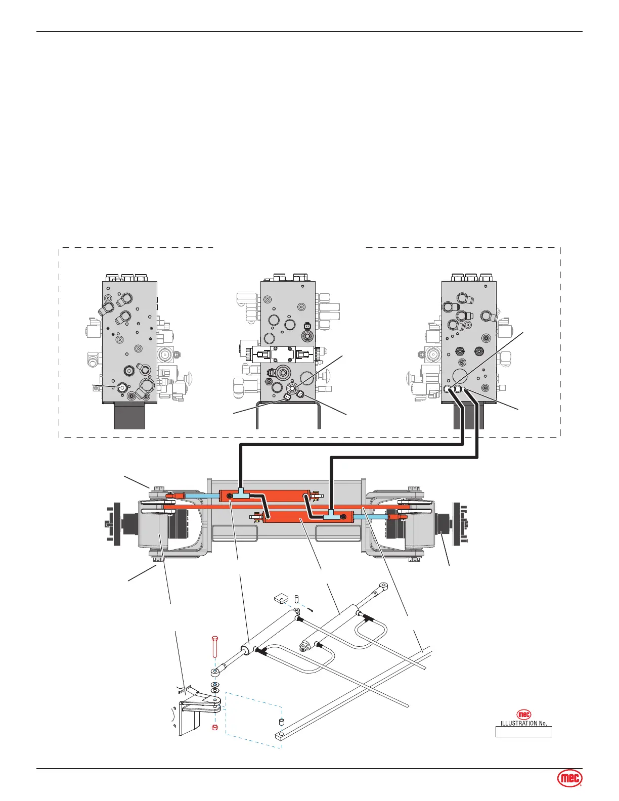
Steering Circuit
Note:Refer to Hydraulic Manifold and Relief Pressure Adjustment Procedure.
Refer to Section 7 for Remove and Install instructions.
Refer to the Parts Manual Section 15 for hose routing.
The steering system consists of the following components:
The wheel motor housings have pivots on the top and bottom, and are mechanically linked
together via a tie-rod.
Steering is accomplished hydraulically by using two (2) double-acting cylinders, and a 4-way 3-
position solenoid-operated, hydraulic directional control cartridge valve.
Maximum steering pressure is limited by the steering relief valve (refer to Relief Pressure
Adjustment Procedure).
Wheel Motor
Tie Rod
Motor
Housing
Pivot
Steer
Relief
Valve
Steer
Control
Valves
Steer
Left
Port
Steer
Right
Port
Steer Left
GRN/RED
Steer Right
ORG/WHT
Motor
Housing
Motor
Housing
Pivot
Left Steer Cylinder
Steer Left Hose
MAIN HYDRAULIC MANIFOLD
Front View Right Side ViewLeft Side View
Steer Right Hose
Right Steer Cylinder
ART_2551
•
•
•