Page 56 Speed Level Series - Service & Parts Manual
January 2019Section 6 - Electrical System
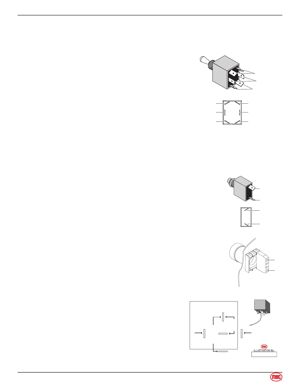
Toggle Momentary Switch
Disconnect wires.
Connect first probe of ohm meter to common terminal.
Test top position
Connect second probe to top normally open terminal.
With the toggle in the neutral (open) position there
should be no reading.
With the toggle UP (closed) there should be a low
resistance.
With the toggle DOWN (closed) there should be no
reading.
Test bottom position
Move second probe to bottom normally open terminal.
With the toggle in the neutral (open) position there
should be no reading.
With the toggle DOWN (closed) there should be a low
resistance.
With the toggle UP (closed) there should be no reading.
Repeat for both rows of two-row switch.
•
•
•
•
•
•
•
•
•
•
•
Common
Normally Open
Normally Open
Normally Open
Normally Open
Common
Normally Open
Normally Open
Common
ART_2564
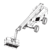
Momentary Button Switch
Disconnect wires.
Connect one probe of ohm meter each terminal.
With the button in the neutral (open) position there should be no reading.
With the button pushed (closed) there should be a low resistance
•
•
•
•
Common
Normally Open
Common
Normally Open
ART_2565
Emergency Stop Button
Disconnect wires.
Connect one probe of ohm meter each terminal.
With the button PRESSED there should be no reading.
With the button RESET there should be a low resistance.
•
•
•
•
Relay
With the #85 terminal grounded, apply voltage to #86
terminal connection.
Confirm normally closed (#87A) contacts are opening.
Continuity with #30 will be broken.
Confirm normally open (#87) contacts are closing.
Continuity with #30 will be made.
•
•
•
ART_2330
RELAY DETAIL
(relay energized)
85 86
87
87A
30
OPEN
CLOSED
B+B−
NORMALLY
NORMALLY
COMMON
SIGNALSIGNAL