14.4.2 Adjusting the
∆∆
P of the equipment
without adjusting the power regulation
(F.R. valve)
Warning: Take great care when removing the
controller, as the chamber for the ram subject
to the controller may be under pressure.
Place the equipment on the ground, stop the
engine, make the contact and cancel any
residual pressure by activating the keys in all
directions.
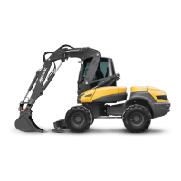
1- Remove the anti-shock controller (1 fig. 1) (the small
bucket ram chamber).
2- Raise the regulation controller into its position.
Ref = 536A0107 (taring at 50 bar).
3- With engine in maximum regime, place the
selector on “MECALAC 1” push the right manipulator
to the right (blocked position) to allow oil to circulate.
4-
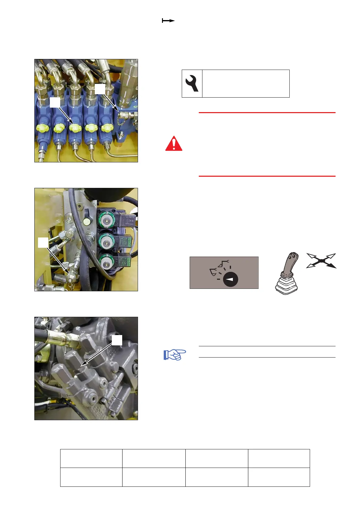
Measure the difference in pressure between
(2 fig. 1) and
(1 fig. 2) using the two manometers.
5- Loosen the lock nut and turn the screw (1 fig. 3)
clockwise in order to increase the
∆∆
P.
Tare the shock absorber (first use).
1- Place the selector on “MECALAC 1” push the
right manipulator to the right (blocked position)
to allow oil to circulate.
2- Loosen the lock nut and turn the screw
clockwise to adjust the pressure
(2 fig. 1)
(50 bar).
28000 12MXT
M1 71
17 and 22 flat spanners
3 male hexagonal spanner
2 manometers, 0 - 600 bar
Fig. 1 SX14 valve block
1
Fig. 2 Assistance pressure unit
1
Operation
Pressure
(bar)
Measurement
(ref. no.)
Adjustment
(ref. no.)
∆∆
P of equipment
17 (+1 -0) 2 fig. 1 and 1 fig. 2 1 fig. 3
2
1
Fig. 3 Equipment pump