1
3- Set the selector to MECALAC 1 and pull the right key
towards the front (blocked position) to allow the oil to
circulate (small chamber in the dipper ram).
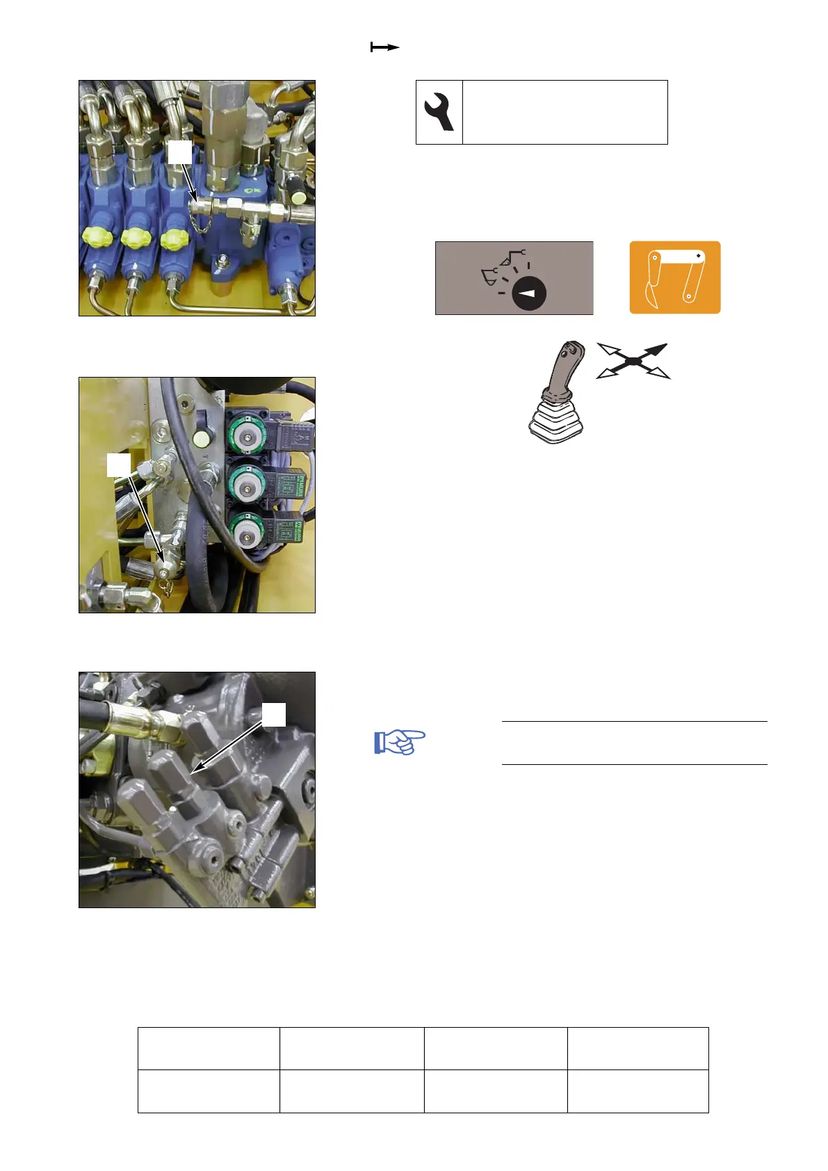
4- Measure the difference in pressure between (1 fig. 3)
and (1 fig. 4) using the two manometers.
5- Turn the screw (1 fig. 5) clockwise in order to increase
the
∆∆
P.
Note: The flow meter kit shall remain installed
for adjusting the power regulation.
28000 12MXT
M1 73
17 flat spanner
3 male hexagonal spanner
2 manometers, 0 - 600 bar
Fig. 3 SX14 valve block