33
TROUBLESHOOTING
NOTE:IfnecessarytoachievetheIMMUNITY
TEST LEVEL, the distance between the
transmitting antenna and compact piezo LED
may be reduced to 1 m. The 1 m test distance
ispermittedbyIEC61000-4-3.
WARNING:PortableRFcommunications
equipment (including peripherals such
asantennacablesandexternalantennas)
should be used no closer than 30 cm ( 12
inches)toanypartofthecompactpiezoLED
device,includingcablesspeciedbythe
manufacturer. Otherwise, degradation of the
performance of this equipment could result.
7 TROUBLESHOOTING
7.1 DiagnosticSystem
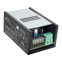
compact piezo LED is equipped with a
diagnostic circuit that allows detecting
operating anomalies and to notify their type
on the control module via a red/green LED
light.
DevicePoweredWithoutPedalActivation
LED Description
GreenON The device is working properly.
Greenandredalternativelyashing
Installation issue:
• potentiometer not connected.
GreenandredON
During the previous work cycle the general
protection has been activated.
GreenONandredashing
During the previous work cycle the tuning
scan failed protection has been activated.
DevicePoweredWithPedalActivation
LED Description
GreenON The device is working properly.
Greenandredon Current limiter activated.
Greenandredalternativelyashing
Installation issue:
• Power supply too low;
• Power supply too high;
• Potentiometer not connected.
Red ON
Generalprotectionactivated:
• Handpiece not connected to the cord;
• Tuning circuit malfunction;
• Cord wire disconnected;
• Handpiece failure.