40 MOM2 ZP-BD03E BD0333FE
7 MOM2 WIN
7.7 Calibration
Required equipment
▪ Stable DC voltage source
▪ Calibrated reference voltmeter
▪ Reference shunts 1 m and 10 m
Procedure
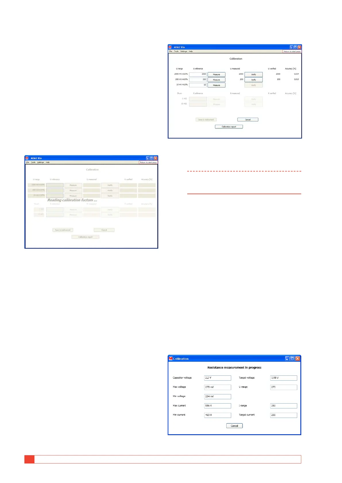
1] Click the "Calibration" button on the Start
page or select "Calibration" from the "Tools"
menu to switch to the calibration page.
The existing calibration factors will be read
from the instrument and the calibration page
will be disabled until it is finished.
Figure 8.7.1 Calibration page. Loading calibration factors
during startup.
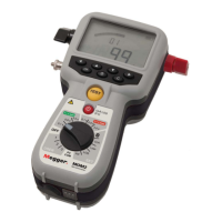
Voltmeter calibration
The voltmeter should be tested in three ranges.
1] Connect the voltage source to the MOM2
sense input, correctly polarized
2] Adjust voltage so that it falls within ±10%
of the stated reference voltage, using the
calibrated voltmeter.
3] Type the value in the U reference column in
MOM2 Win
4] Click the "Measure" button next to the field.
The value measured by the MOM2 will then be
propagated to the "U measured" text field.
New calibration factors will automatically be
calculated.
5] Click the "Verify" button.
The voltage measured with the new calibration
factor will be shown in the "U Verified" field. The
deviation (in percent) from the reference value
will be shown to the right.
6] Repeat from step 1 for the next two ranges.
Figure 8.7.2 Voltmeter calibration
Ammeter calibration
Note The voltmeter in the instrument must be
calibrated before it is possible to calibrate the
Ammeter.
The ammeter is calibrated in an indirectly manner by
measuring the resistance over two predefined shunts
and compare with the reference values. The resistance
is measured with a capacitor voltage suitable for the
voltage and current ranges.
1] Connect the current cables from the MOM2
to the reference shunt
2] Connect separate sense leads from the
MOM2 sense input to the sense outputs of
the reference shunt
3] Enter the value of the shunt in the "R refer-
ence" input field.
The "Measure" button will be enabled if the
resistance is within the limits.
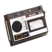
4] Click the "Measure" button next to the field.
When the measurement is started a progress
window is shown, see fig. below. The two
uppermost fields show the measured capaci-
tor voltage and the target voltage.
Figure 8.7.3 Resistance measurement progress window