62%
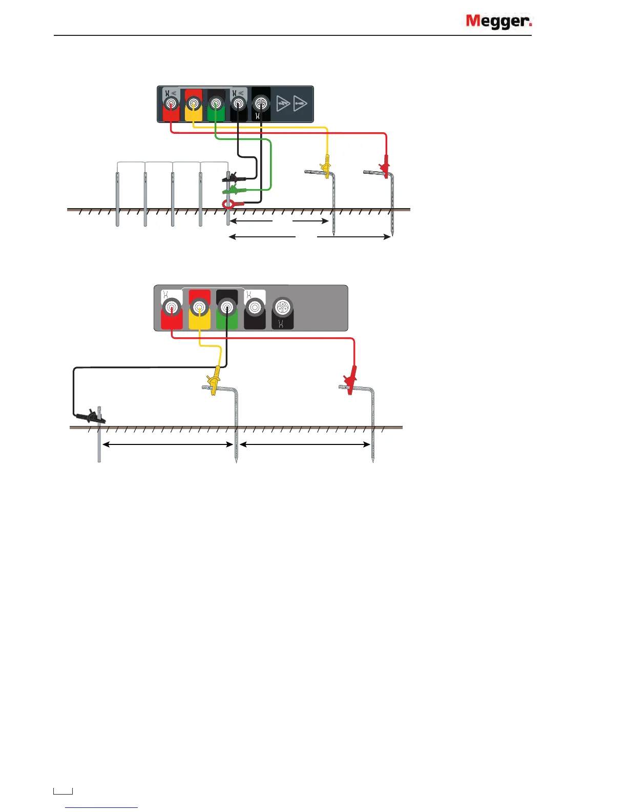
Three terminal test lead set-up
G
F
V
I
C1
E
E/X
CAT IV 300V
CAT IV 300V
CAT IV 300V
CAT IV 300V
Y
V
P1
ES
P2
S
C2
H
15 m to 25 m 15 m to 25 m
P1 P2 C2
Important: The current stake / pin, potential spike and earth / ground electrode must be placed in a straight line.
Important: When running test leads out to each remote stake / pin, take care not to lay them close to each
other. This is to minimise the effect of mutual inductance.
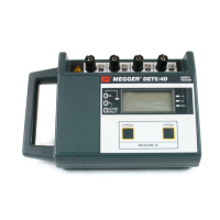
Determine the earth electrode test lead resistance
The earth electrode test lead resistance can be determined separately.
1. Remove the test lead from the earth electrode and connect to the C2 and P2 terminals.
2. Press test.
The lead resistance can then be deducted from the earth resistance measurements.
This procedure is not required if the C1 and P1 terminals are connected by separate test leads.
Note: The result for a three terminal test will include the resistance of the test lead used to connect to the earth
electrode under test. The resistance can be measured by connecting the lead to the P1(X) and P2(Y) terminals,
selecting a 2P test and pressing the test button. This lead resistance can be subtracted from the earth resistance
measurements.
www.GlobalTestSupply.com
Find Quality Products Online at: sales@GlobalTestSupply.com