DET2/3
14
Earth / ground resistance
Earth / ground resistance
Test procedure
Warning: Make sure the circuit is de-energised, before the instrument is connected for measurement.
Note: Manual or Continuous Graphical Mode (see Test modes (page 11).
Step Manual Mode Continuous Graphical Mode
1
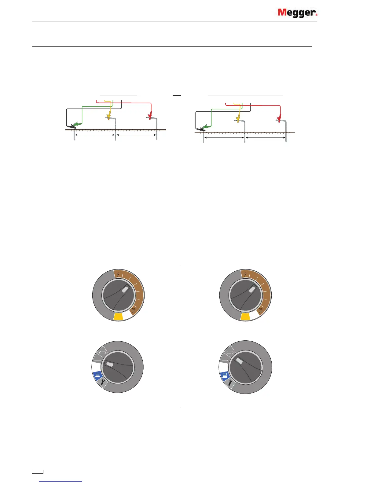
15 m to 25 m 15 m to 25 m
P1 P2 C2
Connect pins / stakes Connect pins / stakes
Note:
Set up test leads and stakes as required by each test (do not connect the test leads to the instrument):
Test Test Method Set-up
4P / 4P ART
3P / 3P ART
Fall of potential
Fall of potential
Fall of potential
Four terminal test lead set-up (page 23)
Three terminal test lead set-up (page 24)
Three terminal ART test lead set-up (page 24)
4P / 4P ART
3P / 3P ART
Slope method
Slope method
Slope four terminal test lead set-up (page 27)
Slope three terminal test lead set-up (page 28)
4P / 4P ART
3P / 3P ART
61.8% rule
61.8% rule
61.8% Four terminal test lead set-up (page 29)
61.8% Three terminal test lead set-up (page 29)
2P Two terminal earth resistance test (page 29)
2 Clamp Two clamp (stakeless) test (page 30)
2
4P
4P
3P
3P
2P
A
Ω
Ω
4P
4P
3P
3P
2P
A
Ω
Ω
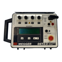
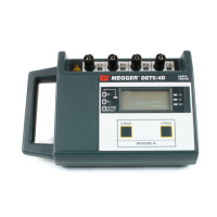
Set the function Set the function
3
MAN
OFF
MAN
OFF
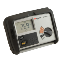
Set the mode Set the mode
OR