4. Voltage, frequency, current and temperature measurement
4.1 Making a voltage measurement
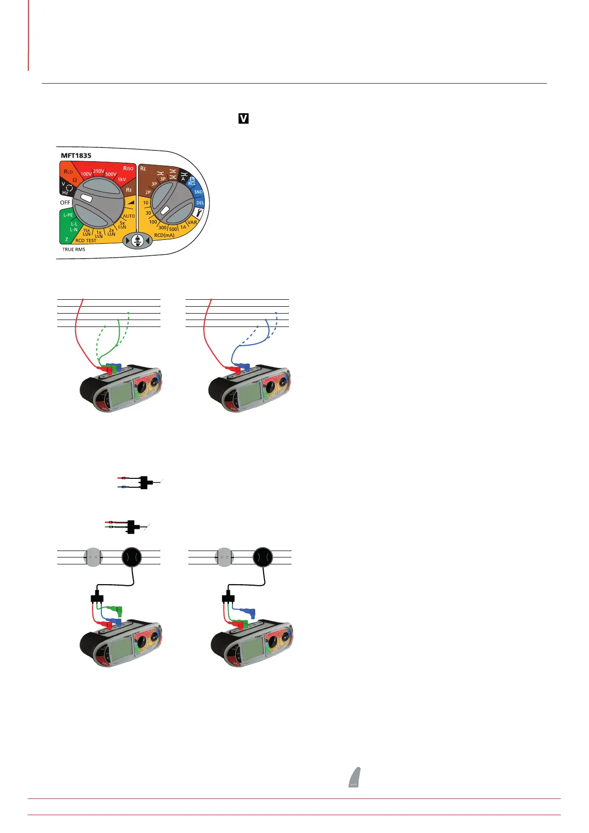
1. Set the Main rotary range knob to volts
(The position of the right hand rotary range knob does not matter)
2. Using two test leads, connect test leads to the L1 (+ve) and L2 (-ve) terminals
L1
L2
L3
N
E
L1
L2
L3
N
E
OR if Using the Mains plug Lead SAI10:
1. Connection (a)
For Live to Neutral measurements, connect the Red connector to the L1 terminal and the Blue connector to the
L2 terminal
2. Connection (b)
For Live to Earth measurements connect the Red test to the L1 terminal and the Green connector to the L2
terminal
L1
N
E
L1
N
E
Connection (a) Connection (b)
NOTE : When connecting all three test leads (eg Phase, Neutral and Earth) or the mains plug test lead, the
voltage displayed is the highest of the three possible voltages.
Pressing either TEST button scrolls through L-E, N-E and L-N individual voltages. When the frequency of supply is
shown, the voltage displayed reverts to the maximum voltage across all 3 terminals.
On models with a dedicated mV range this is selected using the Mode
button to select mV mode.
www.megger.com
MFT1800 series
18
Voltage, frequency, current and temperature measurement