8.13 3 Phase RCD testing
The MFT1800 series is designed to test RCDs on 3 phase installations.
To test RCDs in a 3 phase system each RCD is tested as a single RCD, from Phase to earth. As described in “8.1
Making an RCD measurement” on page 38 to “8.6 5 x I RCD current rating (Tripping test on 30 mA
RCD)” on page 41.
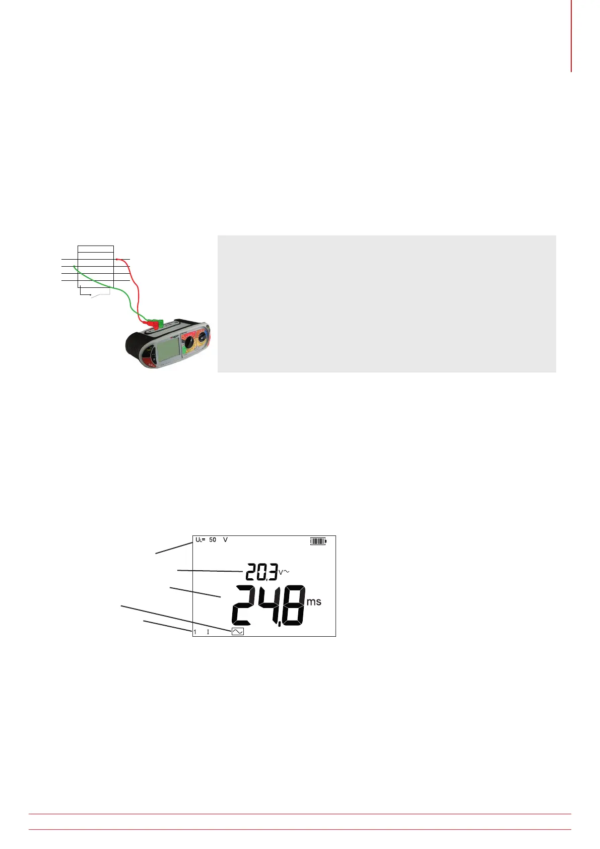
Where no earth is available, the upstream/downstream method can be used. This requires testing across two phases,
as below.
1. To test Phase 1 RCD, connect the MFT Red (L1) terminal to the downstream (o/p) of the RCD to be tested.
2. Connect the Green (L2) terminal of the MFT to the upstream phase of an RCD on a separate phase.
3 Phase RCD
O/P
I/P
P1
P2
P3
N
Test
button
3. Press the TEST button.
4. The MFT will display the trip time of the RCD.
8.14 Touch voltage display
The voltage to which an earth conductor may rise during an RCD test. The limit for touch voltage is 50 V AC or 25 V
AC, depending on the environment.
Touch voltage is caused by excessive resistance in the earth circuit when a load is placed between
the live and earth conductors.
Touch voltage is displayed:
- at the end of an RCD test if the voltage is below the safe limit
- before an RCD test is started if it would exceed the safe limit.
X
Touch voltage limit
Measured touch voltage
RCD Trip time (no trip)
RCD Type
RCD Test mode
Touch voltage is calculated using the nominal trip current of the RCD x Earth resistance. For example:
RCD trip current = 30 mA
Earth resistance = 1000 Ω
0.03 A x 1000 Ω = 30 V
If the calculated touch voltage is less than the Touch voltage limit, the RCD test will proceed. If it is greater than the
limit set, the test is halted.
The Touch Voltage limit is set in section - UL 25 V, 50 V, 60 V
NOTE : The touch voltage is always displayed using the nominal trip current of the RCD (ie 1xI).
www.megger.com MFT1800 series
45
Residual Current Device (RCD) or Ground Fault Current Interrupt (GFCI) testing