7.5 Confidence Meter
TM
for non-trip (3Lo) loop impedance tests.
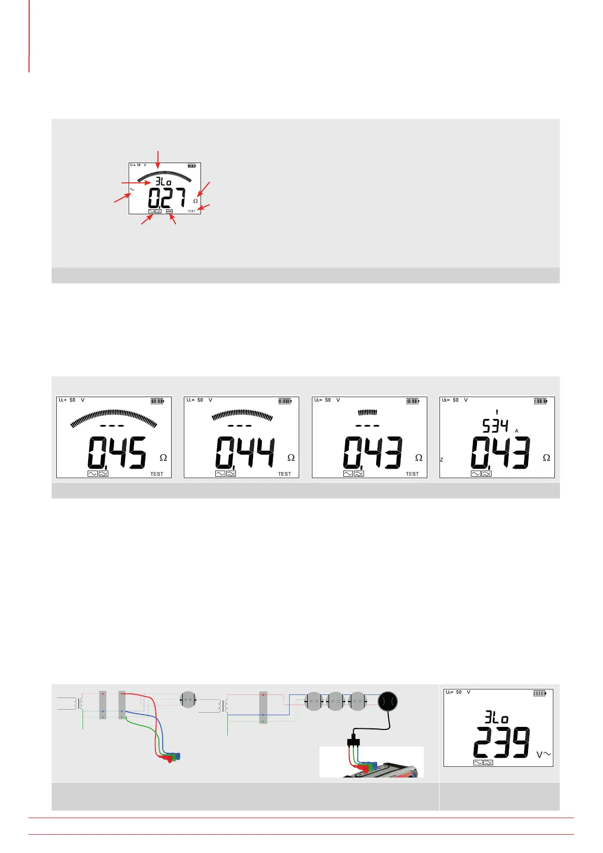
7.5.1. Display information
Confidence
meter
3Lo (3 wire
non-trip)
Mode
indicator
Noise
detected
Standard non-trip
loop impedance
mode test indicator
Non-trip loop impedance
test mode for circuits
with Type B RCD
Test “in progress”
warning
Units of
measurement
Confidence Meter™ Function
Variable test results in a Loop Impedance test are
usually a result of electrical noise on the circuit during
the test. The Confidence Meter analyses this electrical
noise and, if necessary, automatically extends the
duration of the test to arrive at an accurate figure
(as per the instruments stated accuracy).
The analogue arc is used to indicate the degree of
confidence in the accuracy of a measurement.
Figure 1. Instrument Display
During a test the analogue arc will reduce as the degree of confidence in the measurement increases.
As the influence of electrical noise on the measurement is removed the analogue arc reduces down to one element.
At this point the test stops and a final result is shown.
The arc may fluctuate during a test and the shown digital value will change as the Confidence Meter analyses the
electrical noise and corrects the value.
Initial valueStart Analysing noise Finished
Figure 2. Analogue Arc
7.5.2. 3Lo Loop Impedance Measurement
Note: Test leads should not be disconnected during a test, as the sudden interruption of the test current could
be detected by an RCD as a leakage fault and cause a trip. If this is considered to be potentially inconvenient or
hazardous, change 3Lo from AC/A to B mode. This will reduce the risk of the RCD tripping.
Important: It is impossible to guarantee that an RCD will not trip as the RCD may be out of specification, subject to
additional external influences, incorrectly connected or faulty. In this instance alternative methods to test the circuit
characteristics are recommended, for example, the R2 method.
1. Select L-PE.
2. Connect the Live, Neural and Earth test leads of the MFT to a live circuit. The display will show the standard
warning screen.
RCD
g
L
N
E
MCB
L
N
E
MCB
g
Figure 3. 3Lo Connection Options Figure 4. Live Circuit
Warning Screen
www.megger.com
MFT1800 series
34
Loop impedance testing