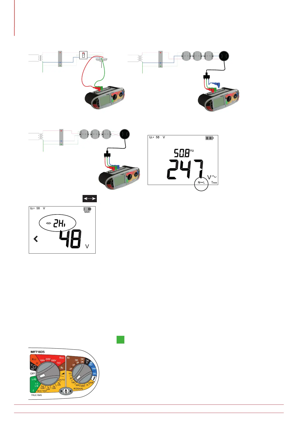
3. Connect test leads as below, with the Red test lead connected to the Red (L1) terminal on the MFT and the Green
test lead connected to the Green (L2) terminal.
L
N
E
MCB
g
L
N
E
MCB
g
The Blue (L3) test lead can be connected to enable “reverse polarity” warnings
N
E
MCB
g
4. Press the Function key to select the “2Hi” mode.
5. Press ‘TEST’ to start the test sequence. This can be automated in SETUP so the test starts when contacting the
circuit. See “11. Setup options” on page 53.
6. On completion of the test, the display will show the loop resistance on the large display segments, and the fault
current on the small display segments.
7.2.3. Earth Loop measurements with an RCD in circuit
Loop testing L-N through and RCD will not trip it, using the 2Hi test mode. However testing Phase to Earth requires a
test that draws less current to help prevent the RCD tripping. It is impossible to guarantee that an RCD will not trip. If
there is a risk associated with tripping an RCD alternative methods should be used for testing the circuit.
Using 3 wire measurement - 3Lo
1. Set the LEFT rotary range knob to the
L-PE
range.
www.megger.com
MFT1800 series
30
Loop impedance testing