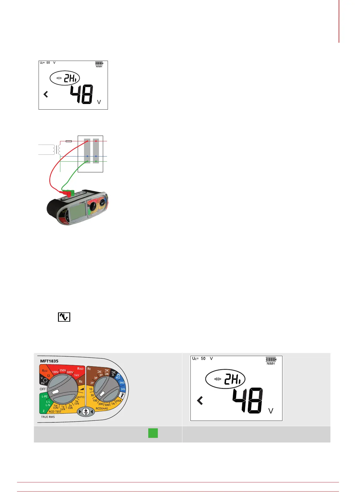
2. Press the Function key <-> to select the “2Hi” mode. The RCD will not trip, so there is no need to use the 3Lo
and 2Lo modes.
3. Connect test leads as below, with the Red test lead connected to the L1 (Red terminal on the MFT and the Green
test lead connected to the Green (L2) terminal.
L
N
E
MCB
RCD
g
4. Press TEST to start the test sequence. This can be automated in SETUP so the test starts when contacting the
circuit. See “11. Setup options” on page 53.
5. On completion of the test, the display will show the loop resistance on the large display segments, and the fault
current on the small display segments.
Reverse Polarity warning:
The 3rd test lead can be connected to Neutral (L3) but is not used in the ‘2Hi’ Phase-Earth measurement.
With the 3rd lead connected the MFT will show a Phase-Neutral reversed connection if present.
A warning is displayed if there are any disturbances to the circuit under test during the test sequence. The display will
show the
symbol. The loop impedance reading may have been compromised by the circuit interference. Repeat
the test.
7.2.2. Zs and Zdb loop measurements without RCD - eg Zs, Zdb etc.
1. Set the LEFT rotary range knob to the
L-PE
range
2. Press the Function key <-> to select the “2Hi”
mode
www.megger.com MFT1800 series
29
Loop impedance testing