18.2 F.2 Principle of operation (three-terminal resistance measurement using ART)
The classic three-terminal test method has a
disadvantage, namely that the electrode under test
must be disconnected from the system it is supposed
to protect in the event of a power system fault. The
reason for this is that the injected test current will
take all possible routes to ground and not all of it will
necessarily flow through the electrode under test.
In this case, the instrument will make a reading of
the entire earthing network, not just the individual
electrode.
By using a current transducer (the Megger
MCC1010) to measure the current flowing through
the electrode under test as a fraction of the total test
current injected, the instrument can determine the
individual resistance. This arrangement is shown in
Figure 11.
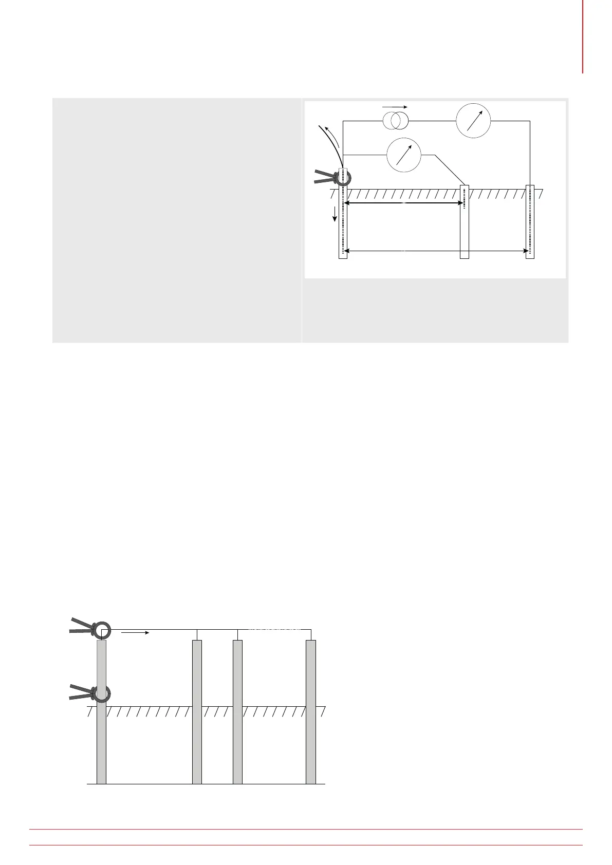
A
Earth electrode
under test
Connection
to rest of system
B
C (H)P (S)X (E)
I2
I1
Potential stake
MCC1010
Current stake
V
I
Figure 11: Schematic for three-terminal resistance
measurement using
In this configuration, the injected test current I splits along two paths into I1 (flowing into the connected earthing
system) and I2 (flowing into the electrode under test, i.e. I=I1+I2. The resistance of the electrode under test is
calculated as R=V/I2 or R=V/(I-I1). The current transducer (MCC1010) measures I2 and feeds this value back to the
instrument.
18.3 F.3 Principle of operation (two-clamp stake-less resistance measurement)
In this example, the electrode under test is connected to a network of other electrodes. It is either impractical or
unsafe to disconnect an individual electrode for testing. Also, there might be insufficient space to perform a classic
three-terminal resistance measurement. The stake-less test method using both MVC1010 and MCC1010 can be used
to obtain a measurement for the electrode under test.
A defined test voltage is injected into the system using the MVC1010, inducing a current, I, to flow and be measured
by the MCC1010. The model shown in Figure 7 can be simplified to the resistance of the electrode under test, Rx and
the resistance of the other electrodes in parallel, i.e. R1 || R2 || … || Rn.
Therefore, the current induced by the test voltage is I=V/[Rx+(R1 || R2 || … || Rn)]. It follows that as the resistance of
the other electrodes in parallel approaches zero, then the resistance measured, approaches the value of the electrode
under test.
Earth electrode
under test
Connection
to rest of system
X (E)
I
I
V
R2R1Rx
MCC1010
MVC1010
Rn
Figure 12: Schematic for two-clamp stake-less resistance measurement
www.megger.com MFT1800 series
63
Appendix F - Earth resistance testing – Basic principles