18. Appendix F - Earth resistance testing – Basic principles
18.1 F.1 Principle of operation (three-terminal resistance measurement)
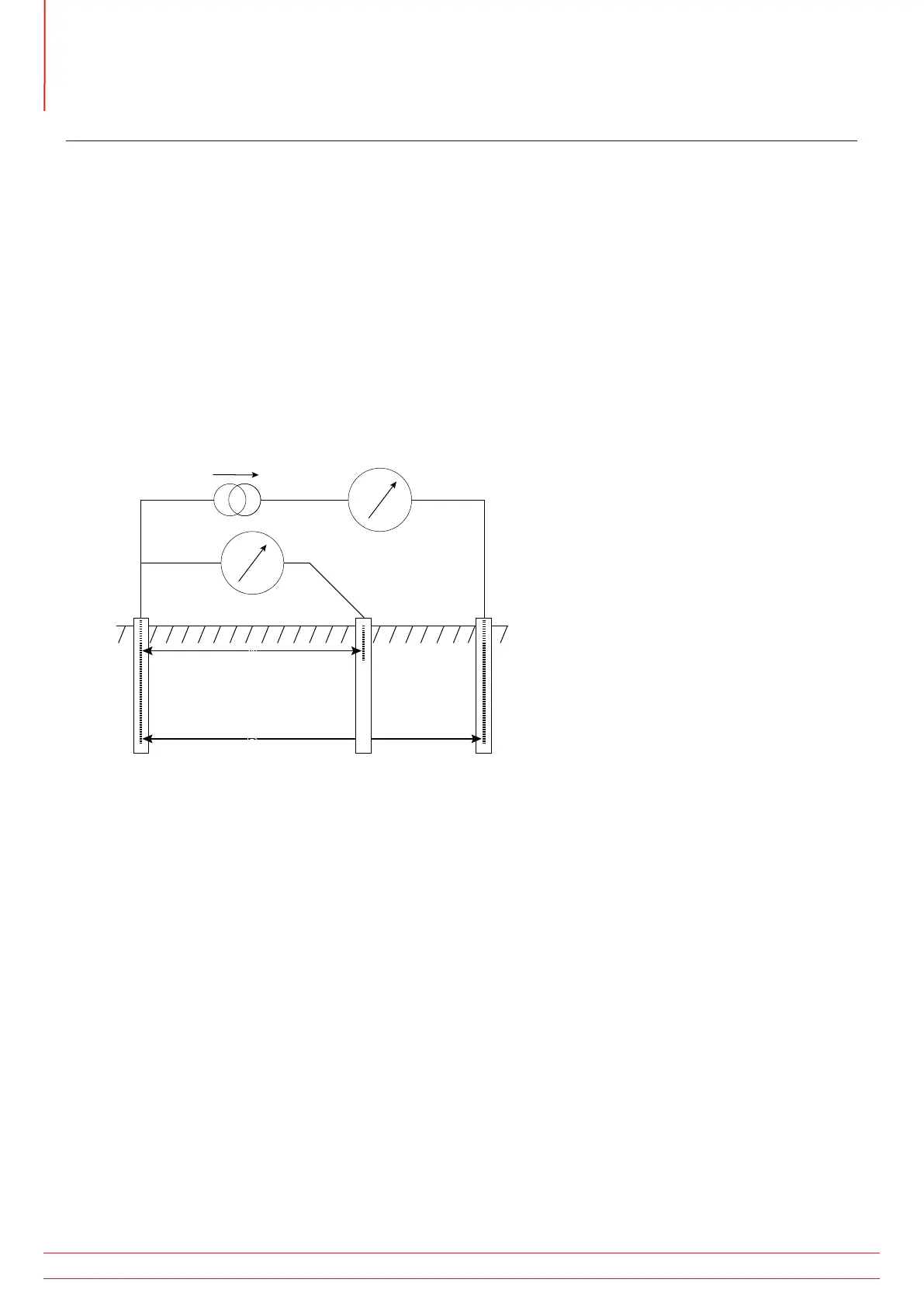
The classic “fall of potential” test is used to accurately measure the resistance of an earth electrode using auxiliary
stakes driven into the soil, which form a circuit for the test current injection and voltage measurement as used for the
two-terminal method.
The MFT injects an AC current of known magnitude into the system under test and measures the voltage developed
across it as shown in Figure 4. The system resistance is a simple ratio as per ohm’s Law. In this case, the potential
stake is moved by fixed increments in a straight line between the electrode under test and the current stake. At each
location, the resistance is calculated as R=V/I. A graph of resistance versus potential stake position is plotted and the
resistance of the electrode under test is taken to be the point at which the curve is flattest.
Empirical testing has shown that with suitably positioned stakes, this method can be shortened by placing the
potential stake at a distance of approximately 62% between the electrode under test and the current stake,
i.e. at A = 0.62 x B.
Earth electrode
under test
C (H)P (S)X (E)
V
I
Potential stake Current stake
A
B
Figure 10: Schematic for three-terminal resistance measurement
www.megger.com
MFT1800 series
62
Appendix F - Earth resistance testing – Basic principles