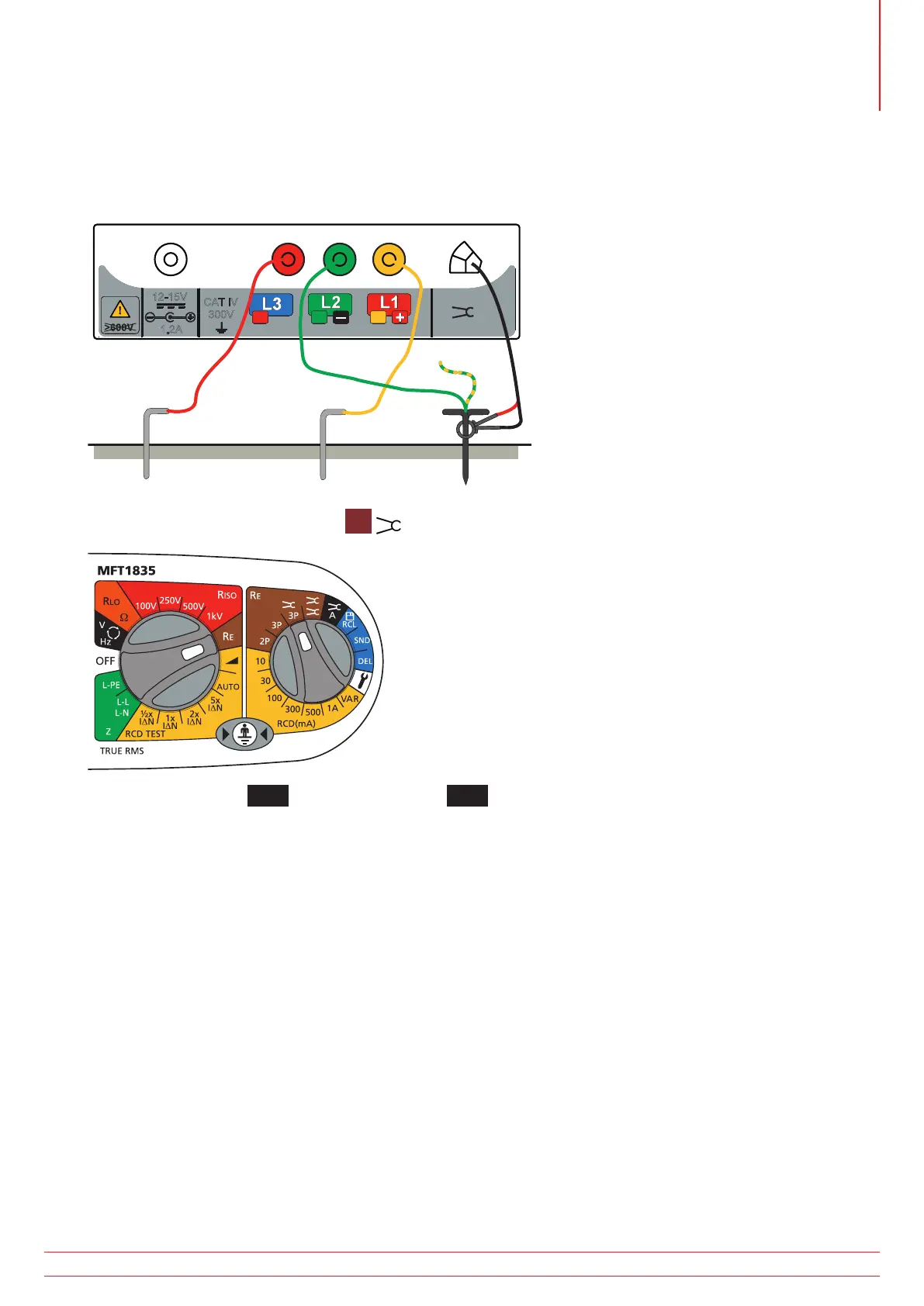
10.5 Making a measurement – Three terminal resistance measurement using ART
1. Connect the instrument as BELOW. Position the MCC1010 below the point where the Green Lead is attached to
the Earth Conductor. In practice the MCC1010 can be positioned directly on the Electrode under test, at a point
below where the green Lead is attached to the the Earth conductor.
I
CAT IV
300V
12-15V
1.2A
H
SE
Electrode
under test
Potential
stake
Current stake
2. Set the rotary selector switch to the
3P
position.
3. Press and release the
TEST
button [by holding the
TEST
button, the resistance measurement will be continually
updated].
The instrument will perform pre-measurement checks, the status of which will be indicated on the display. The three-
terminal resistance reading using ART will be displayed
Under certain circumstances, the instrument may display a noise warning. This means that interference has been
detected which may impair the accuracy of the measurement. In particular, the reading could be lower than the
actual resistance. The resistance of the electrode or system must be verified by an alternative method.
NOTE :
The instrument will display the warning triangle and an excessive noise voltage indicator if the ground noise
voltage is above 20 V pk-pk (7 Vrms).
The instrument will display the warning triangle above 2 A – no ART testing is possible under this condition.
The instrument will display the warning triangle and an over-range condition above 20 A – no ART testing is
possible under this condition.
Ensure that the MCC1010 jaw mating surfaces are free of dust and contamination and that they contact
completely when the MCC1010 is closed.
Currents carried by conductors in close proximity to the MCC1010 may affect calibration and reduce the
accuracy of measurements made.
Re/Rs ratio must be less than 100, where Re = Earth resistance, Rs = Shunt resistance
www.megger.com MFT1800 series
51
Earth resistance measurement