18
Test procedure
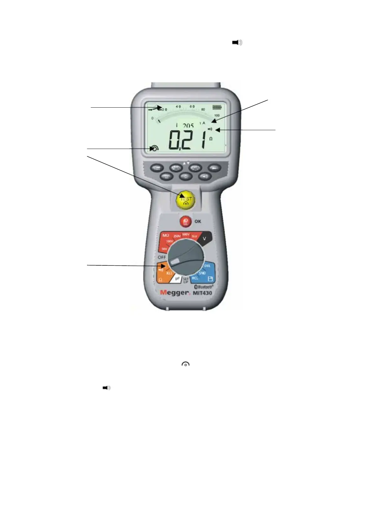
(refer to Figure 9)
Figure 9 Continuity test and buzzer
1. Turn the instrument ‘O
by rotating the selector switch to the desired position.
2. If required the test lead resistance can be set to Zero (null) by shorting the test leads
together and pressing TEST. The null [
] symbol will show when this has been
achieved and the display will read 0.00 .
3. Press the [
] button to enable/disable the audible buzzer function. When enabled, the
sounder symbol will be shown on the screen display. The pass threshold is set to 2 by
default, but is adjustable, as defined in Setup, see section 13.
Note that the buzzer defaults to OFF on power-up.
4. Connect the test leads to the isolated conductor(s) under test.
5. Observe the test result, displayed automatically. The auxiliary display indicates the
actual test current (e.g. 205 mA. The maximum is defined in section 13, setup menu.
Contact
indication
Step 1:
Continuity test
current
Step 3:
Buzzer ON/OFF
Step 4:
Connect test
leads to
conductor(s)
Step 2:
Lead null
www.GlobalTestSupply.com
Find Quality Products Online at: sales@GlobalTestSupply.com
 Loading...