CashFlow
952X / 952Xe / 9510 User Guide
MEI., 2005 Page 24 Rev: G2
Route Inhibit Connector
The route Inhibit connector, when used in parallel mode, gives a signal when specific exits,
(external to the product) are in a “Full” condition. Signals from the machine ensure that,
while the “Full” condition continues, further coins/tokens directed to that exit will be re-routed
to an alternative exit.
When in BCO or HI
2
mode this will depend on the machine signal sent to the
CF952X/CF952Xe.
Notes:
1. In order to inhibit a particular route, 0V must be applied to its respective pin.
2. An alternative route must always be of a lower priority
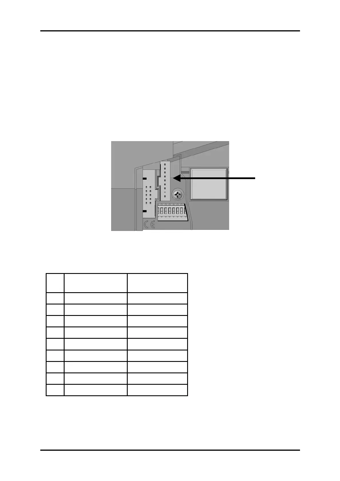
Route inhibit connections are via a 9 way header from the standard PCB. This header is a
single row of 9 pins on a 0.1 inch grid. The pin size is 0.025 inch square.
Pin Description for
(CF9528/CF9528e)
Description for
(CF9524/CF9524e)
1 Full 1 (d)
2 Full 2 (c)
3 Full 3 (a)
4 Full 4 (b)
5 Full 5 C
6 Full 6 D
7 Full 7 B
8 Polarised Polarised
9 Ground Ground
9 Way Route
Inhibit Connector
 Loading...