4 Description of the device
14
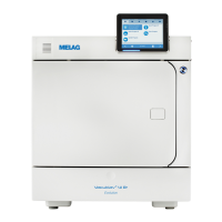
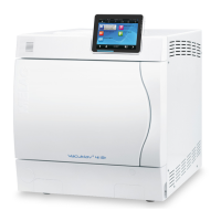
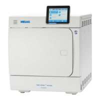
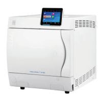
Views of the device
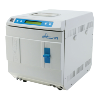
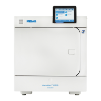
Fig.1 : View from front
1 Tank lid of the internal storage
tank
2 CF card slot
3 Colour touch-display
4 LED status bar
5 Energy-saving key
6 Door (swings open to the left)
7 Opening for door opening in an
emergency*)
8 Power switch (covered,
accessible from the side)
9 Ethernet connection
10 Overheat control reset button
11 Allen key 5 mm to open the door
in an emergency
12 Quick coupling for emptying the
storage tank
13 Front device foot (adjustable)
14 Manometer for pressure display
on the double-jacket steam
generator
*)
*) behind cover
22
23
24
20
16
19
15
18
27
21
26 25
17
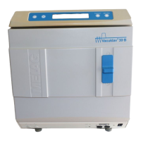
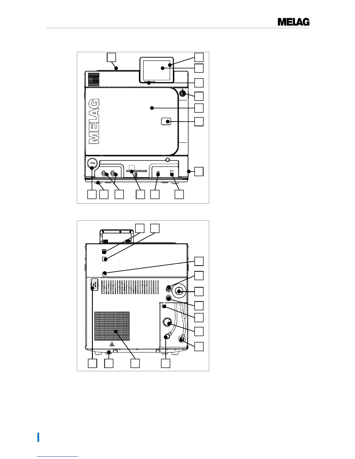
Fig.2 : View from rear
15 Ethernet connection
16 Ethernet connection, optional
(upgradeable)
17 Optional connection of a Flex
display
18 Spring safety valve chamber
19 Sterile filter
20 Spring safety valve double jacket
21 Emergency overflow
22 One-way discharge
23 Feed water inflow (swivel screw
connection for Ø8x1 hose,
alternative straight)
24 Connection pressure release
25 Cooler
26 Rear device foot (fixed)
27 Power cable connection