192 of 289
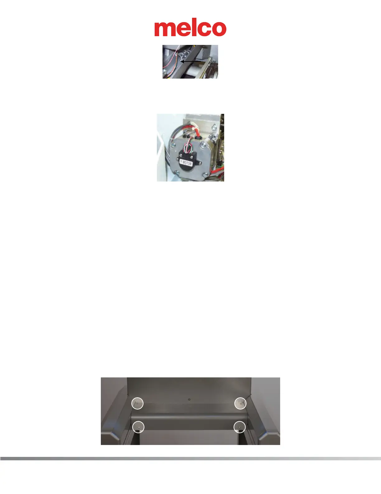
Figure 2 - Right Wire Channel
10. Pull the color change harness to the back of the machine out of the right wire channel, removing
any twist-lock cable ties that connect the harness to adjacent ones.
Figure 3 - Harnessing Routed Under Y-Motor
11. Pull the color change harness from under the y-motor, removing any twist-lock cable ties that con-
nect it to the adjacent harnesses.
12. Run the color change motor lead end of the replacement harness underneath the thread tree
base from the right wire channel and pull the harness through until about 3 inches extend from
the front of the thread tree base. Connect the color change harness to the color change actuator
interface cable.
13. Apply a single twist-lock cable tie in front of the thread tree base to all of the harnesses that run
underneath the thread tree base and neatly bundle them together.
14. At the back side of the thread tree base, apply a twist-lock cable tie on the harnesses and bundle
them neatly together.
15. Pull the harnesses that run from the back side of the thread tree base towards the right channel
and tie all of them to the adjacent harnesses that run into the right wire channel.
16. Run the harness in the right wire channel all the way to the y-motor area, run it between the
y-motor mounting bracket and the y-motor. Use a twist-lock cable tie to bundle the harnesses
together at both sides of the motor.
17. Remove cover for the main PCB.
a. Remove the 4 screw(s) that hold the main PCB cover in place.