206 of 289
7. Remove any twist-lock cable ties from the left LED cluster harness and pull it through the left wir-
ing access hole in the lower arm body to the Main PCB.
8. Disconnect the A/C power input cord and the external Ethernet cable from the back of the
machine.
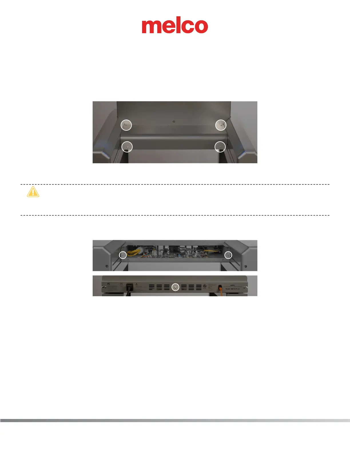
9. Remove cover for the main PCB.
a. Remove the 4 screw(s) that hold the main PCB cover in place.
b. Remove the PCB cover.
•
CAUTION!! Be careful not to drop metallic hardware or tools onto the Main PCB while it is
exposed. Doing so can result in severe damage to the electronics that might be expensive to
repair.
c. Once the main PCB cover is removed loosen but do not remove the 2 PCB securing tray screws
in the front and fully remove the securing plate screw in the rear.
10. Gently slide the main PCB mounting tray forward to gain full access to the main PCB.
11. Remove the wire tie from the left and right LED cluster harnesses and disconnect the right LED
cluster harness from the Main PCB at connector location “Light 1/2”.
12. Connect the new LED cluster harness to the left LED cluster assembly and run it through the z-mo-
tor mounting bracket and use a twist-lock cable tie to tie it with the adjacent harnesses to the
z-motor mounting bracket (Figure 2).
13. Run the LED cluster harness following the adjacent harnesses down to and through the left lower
arm access hole (Figure 3).
14. Run the LED cluster harness through the left lower arm access hole to around the left inside pe-
rimeter of the base and connect it to the Main PCB at connector location “Light 1/2”.
 Loading...
