207 of 289
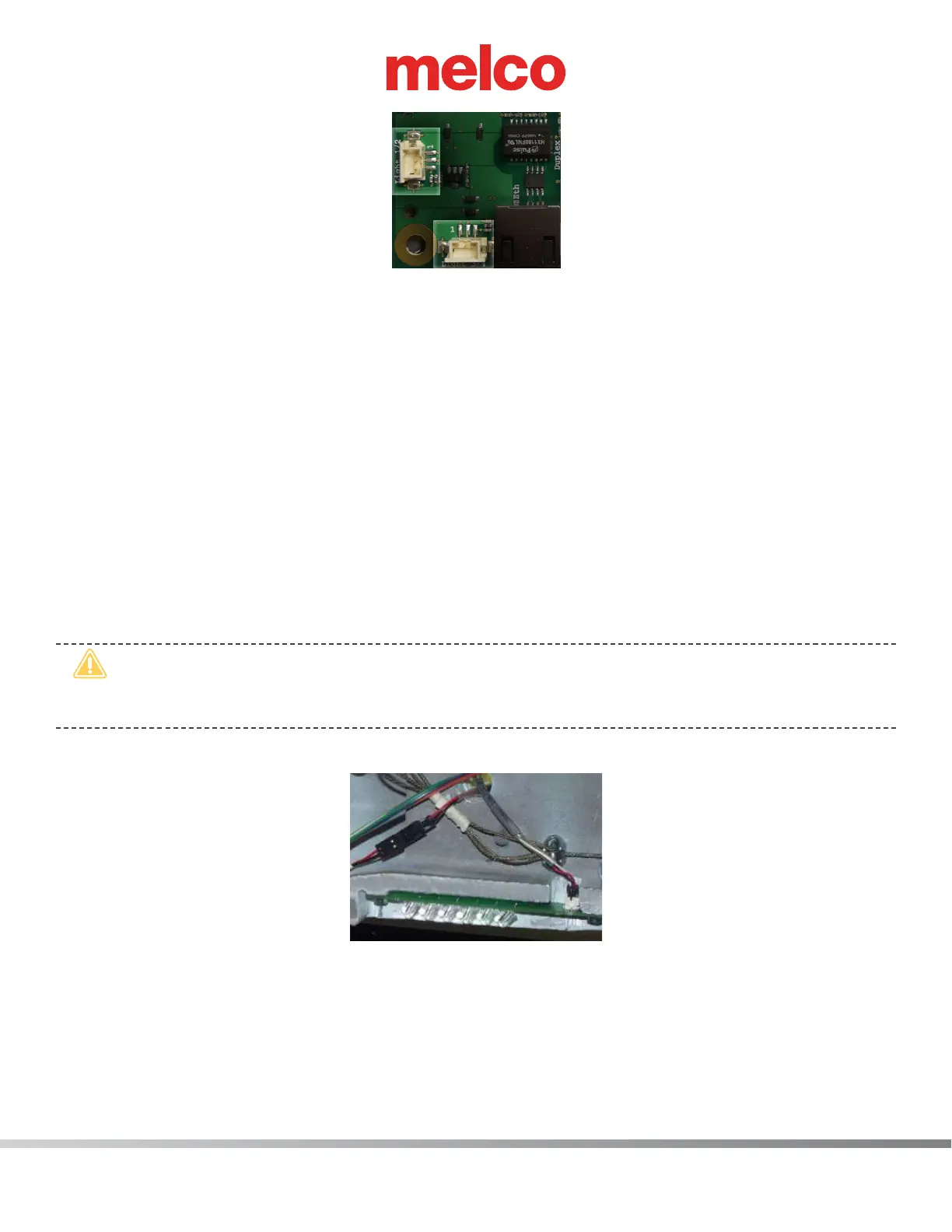
Figure 5 - LED Cluster Harnesses Connected at Main PCB
15. Place the LED cluster harnesses at the main PCB as shown in Figure 5 above.
16. Install the left upper arm front cover and tighten the screws to the torque specications.
17. Replace the EMI cover by following steps 9-10 in reverse order.
18. Install the remaining covers in the reverse order that you removed them and tighten the screws to
the torque specications.
19. Turn the machine ON and verify that the LEDs come on in the left LED cluster assembly.
Right LED Cluster Assembly:
1. Turn the machine ON.
2. Color change to Needle 1.
3. Turn the machine OFF.
•
CAUTION!! Use extreme care not to drop metallic objects, tools, or other conductive material
on the Main PCB when you have the base cover removed. If you drop such objects on the Main
PCB, it can severely damaged the electronics which will be very expensive to repair.
4. Remove the right upper arm front cover, right upper arm cover and the base cover.
Figure 6 - Right LED Cluster Harness
5. Disconnect the LED cluster harness from the left LED cluster assembly.
6. From the back side of the right upper arm, pull the harness through the access hole located just
above the x-cable clamp (Figure 5).
7. Pull the harness through the right access hole to the back of the machine, removing any twist-lock
cable ties that tie it to the adjacent harnesses and pull it through the right lower arm access hole.
 Loading...
