76 of 289
Trimmer Replacement
NPT Printed Circuit Board Assembly Replacement
1. Disconnect the A/C power input cord and the external Ethernet cable from the back of the
machine.
•
You must disconnect the power before proceeding.
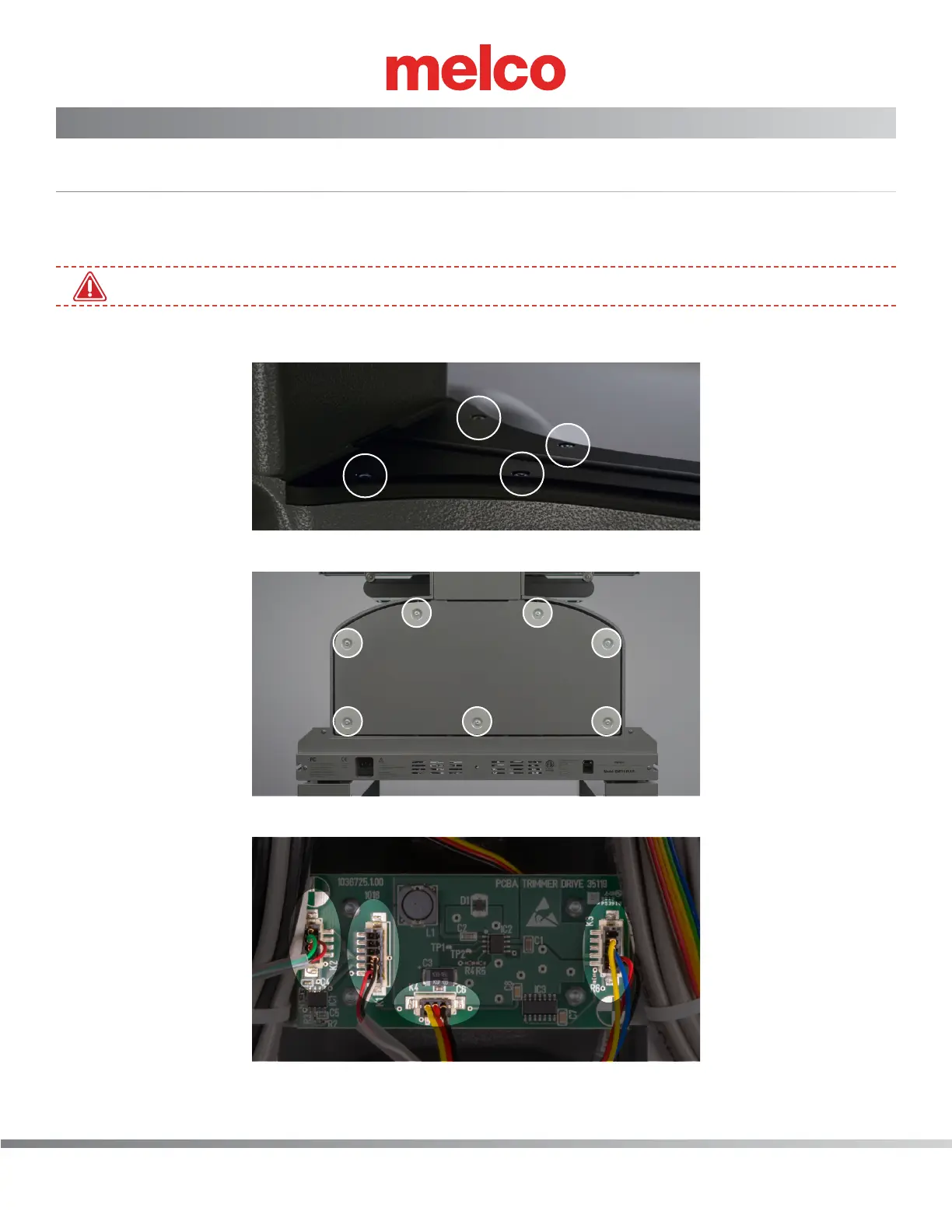
2. Remove the lower arm top cover by removing four (4) M4x12MM Screws.
3. Remove lower arm rear cover (7 M4 Socket head cap screws)
4. On the trimmer PCBA locate the connections labeled K1, K2, K3 and K4 and disconnect.