77 of 289
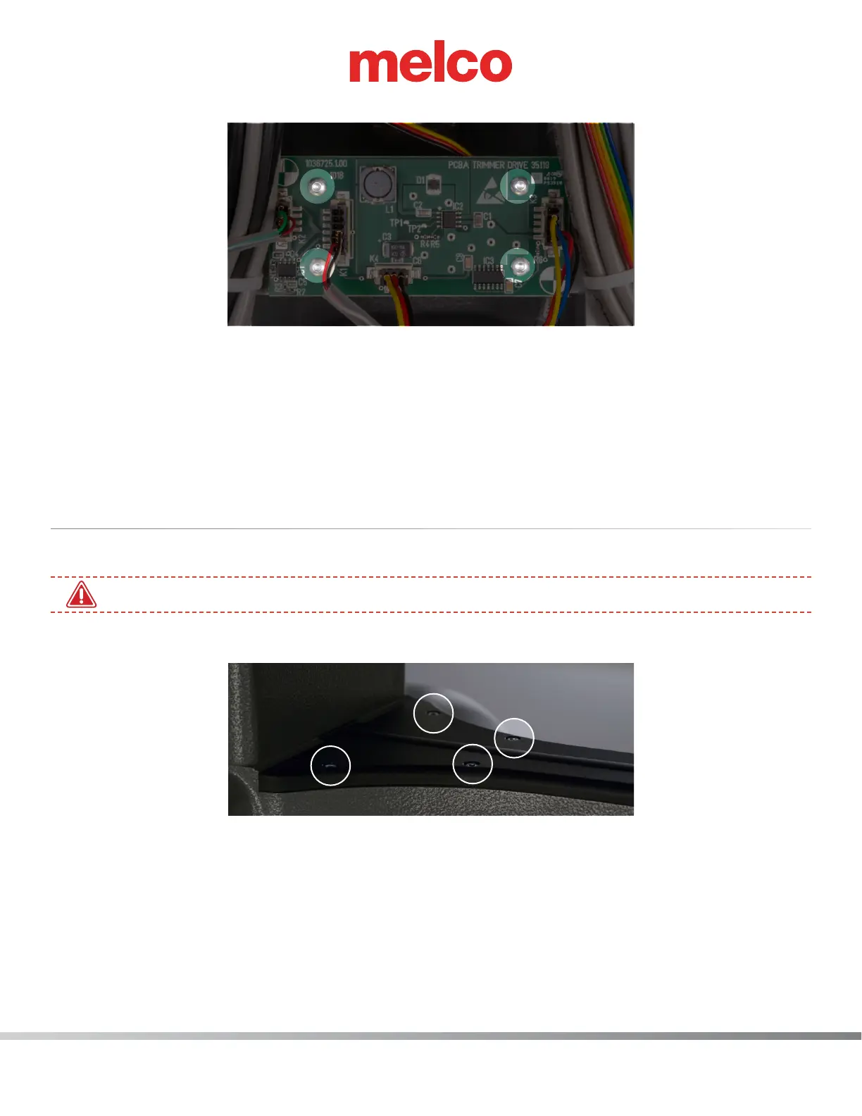
5. Uninstall the trimmer PCBA by removing the (4) M4x6mm Btn Hd Cap Screws.
6. While making sure the connection labeled K2 is on the left,. install the new trimmer PCBA.
7. On the trimmer PCBA locate the connections labeled K1, K2, K3 and K4 and connect the corris-
ponding harnesses.
8. Reassemble all the covers previously removed in steps 2 and 3. Don’t forget to also reconnect the power.
9. Check the Functionality of the board. Maintenance>Steppers>Map sensor and run through the
trim steps to ensure that the new board works.
NPT Sensor Replacement
1. Disconnect the A/C power input cord and the external Ethernet cable from the back of the machine.
•
You must disconnect the power before proceeding.
2. Remove the lower arm top cover by removing four (4) M4x12MM Screws.