FOCKE MELER GLUING SOLUTIONS
3-8
INSTALLATION
• Output disabled_disabled input signal for each hose-applicator output
via a non-voltage contact. With a closed contact, the output remains
activated (output on); with an open contact, it is deactivated (output off).
• Motor start up_for each pump installed, the motor start up may be
controlled by closing an external non-voltage contact.
• Motor speed set point_for each pump installed, the rotational speed of
the motor (and therefore, the pump) may be controlled by means of a 0
to 10V DC external signal.
• Failures output in pump control card_output from a non-voltage
contact that communicates normally to a warning light beacon the
failure from the pump control card.
Warning: Risk of electric shock. Carelessness may cause injuries or death.
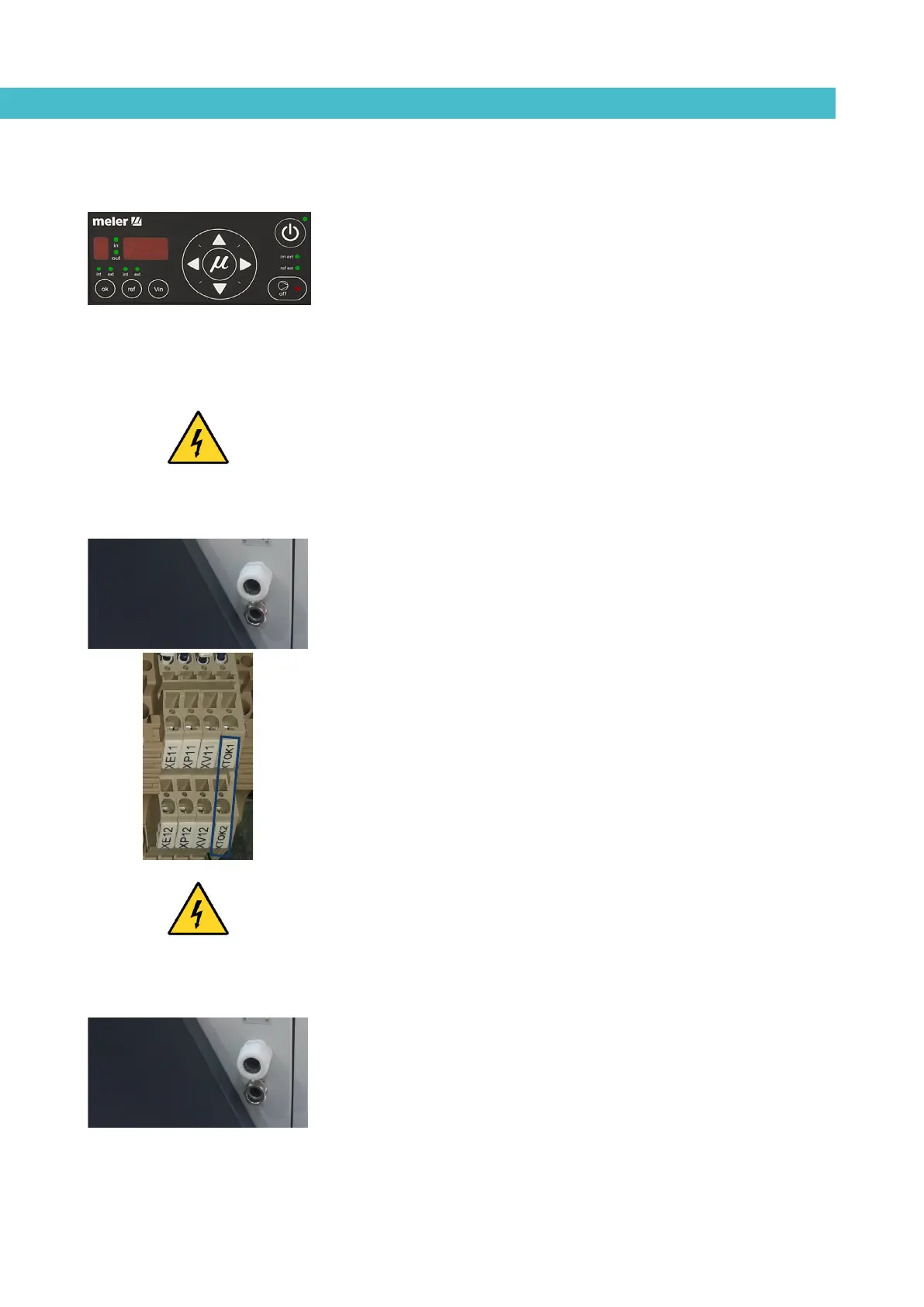
Temperature ok
1. If only this signal will be connected, use a 0.5 mm
2
two-wire cable.
2. Thread the power cord (max. Ø12.5 mm) through the electrical wall
bushing Pg13 and fasten it to the inside anchor, making sure that the
cord reaches the power card connector.
3. Connect the two wires from the start-up signal to the terminals XTOK1
and XTOK2. This is a double terminal, which makes it necessary to
connect each wire in one of the two holes in the terminal. Since this
contact is not under voltage, there is no connection polarity.
4. Make sure that the cables are firmly attached by the terminal screws.
5. Make sure that the cable is well connected and that its path through
the electrical cabinet presents no risks of snagging, being cut or any
other accidental deterioration.
Warning: It must be connected to 24 AC or DC voltage with a maximum
current of 500mA. If you connect this signal to 230V load current cannot be
less than 50mA.
External Standby
1. If this is the only signal being connected, use 0.5 mm
2
two-wire cable.
2. Open the electrical cabinet door as far as possible. Thread the power
cord (Ø4-8 mm) through the wall bushing Pg13 and fasten it to the
inside anchor, making sure that the cord reaches the power card
connector at the position where it will be installed.
3. Remove the connector from the card and connect the two cable wires
to their corresponding connector terminals: